Oil-guiding shaft

a technology of oil guiding shaft and oil guiding shaft, which is applied in the direction of engine components, mechanical equipment, and gearing details, etc., can solve the problem of relatively high manufacturing cos

Inactive Publication Date: 2006-08-31
ZF FRIEDRICHSHAFEN AG
View PDF12 Cites 19 Cited by
  • Summary
  • Abstract
  • Description
  • Claims
  • Application Information

AI Technical Summary

Benefits of technology

[0018] Moreover, it is advantageous for the tube to have a connection area at least at one of its ends, by means of which it is supported and / or mounted on the wall of the shaft's inner space and for the oil-guiding ducts to be sealed with respect to one another.
[0020] The insert in the shaft's inner space can be made either as a hollow section or as a solid section. A tube made as a hollow section, however, has the advantage that its inner space can be used within the shaft's inner space as one of the ducts for the oil.

Problems solved by technology

As is made clear by the above explanations, the creation of a plurality of oil-guiding ducts in thin shafts has until now been achieved only very imperfectly because their design structure is complex and manufacturing costs are therefore relatively high.

Method used


Image

  • Oil-guiding shaft
  • Oil-guiding shaft
  • Oil-guiding shaft

Examples


Embodiment Construction

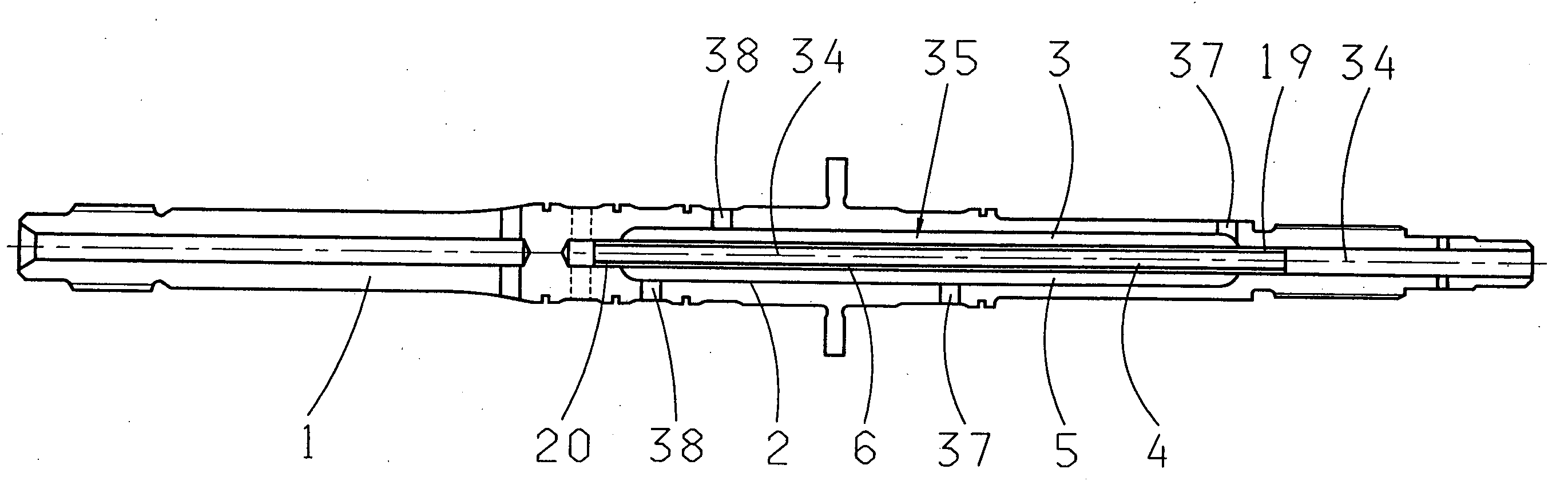
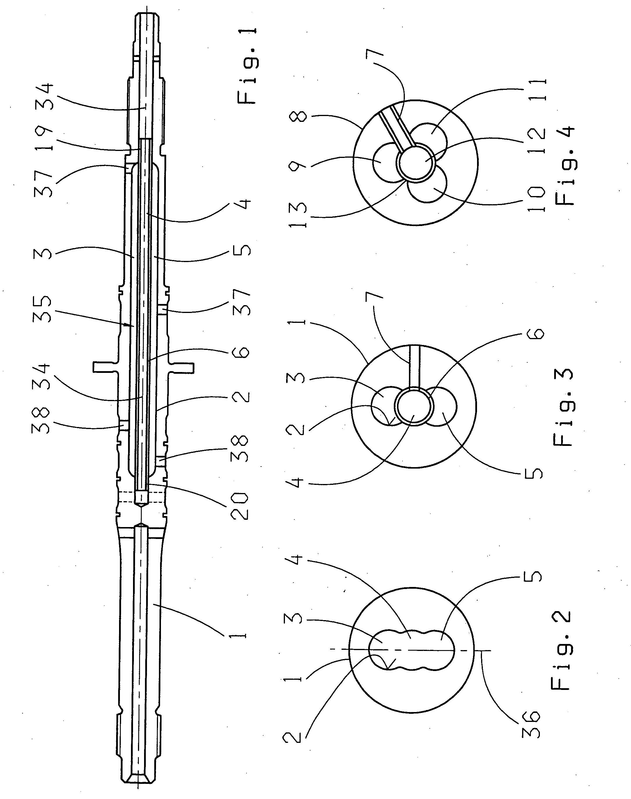
[0031]FIG. 1 is a longitudinal cross-section through a transmission shaft 1, in whose central area an axially extending hollow space is formed which, in what follows, will be referred to as a shaft's inner space 35. This inner space 35 of the shaft comprises three channels 3, 4, 5 which are still open in the pre-assembly condition and which, in the structure chosen for FIGS. 1 to 3, are formed as three circular bores arranged adjacent to one another and overlapping.

[0032] When a tube 6 is inserted into the inner shaft space 35, the tube separates the three channels 3, 4, 5 in a pressure-tight way so that they can, for example, be used as control pressure ducts independent of one another.

[0033] As is clear from FIG. 1, the tube 6 is inserted at one end 20 rotationally fixed in a blind hole of the shaft 1, while the other end 19 of the tube 6 is fitted into the central bore of the shaft 1.

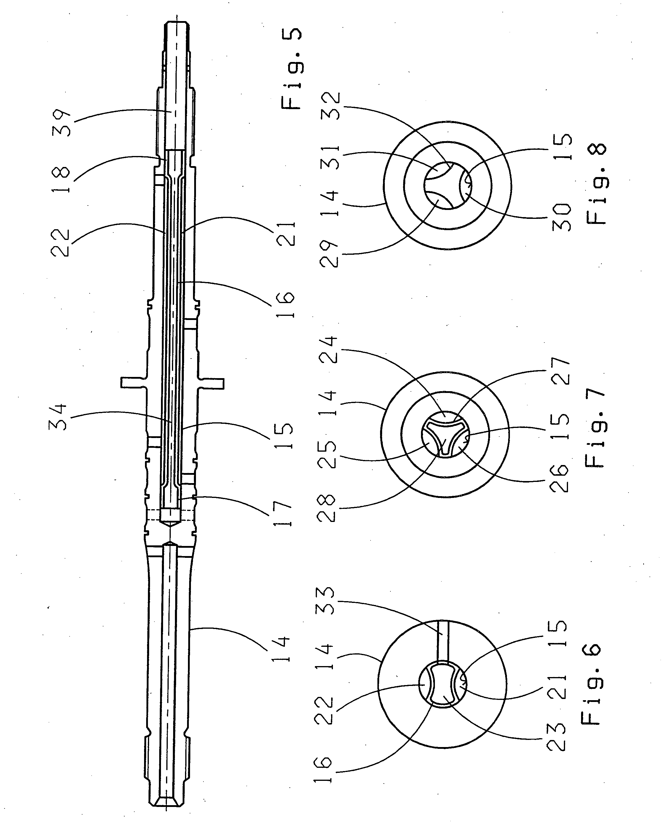
[0034] Furthermore, it can be seen from the sectional representation through the shaft 1 in FI...


PUM


Abstract

An oil-guiding shaft (1, 8) with an inner shaft space (35) coaxial with or axis-parallel to the longitudinal axis (34) of the shaft and with mechanisms arranged in the inner shaft space (35) for dividing the inner shaft space into at least two oil-guiding ducts separated from one another. To enable a plurality of oil-guiding ducts to be produced in a comparatively thin shaft (1, 8), the invention proposes that the ducts (3, 4, 5, 9, 10, 11, 12) are formed as ducts (3, 4, 5, 9, 10, 11, 12) open along their length on the inside wall (2) of the shaft (1) and separated and sealed from one another by a tube (6, 13) inserted into the inner shaft space (35).

Description

[0001] This application is a national stage completion of PCT / EP2004 / 006962 filed Jun. 28, 2004 which claims priority from German Application Serial No. 103 33 432.7 filed Jul. 23, 2003.FIELD OF THE INVENTION [0002] The invention concerns an oil-guiding shaft. BACKGROUND OF THE INVENTION [0003] In many areas of technology, shafts are known through an axial bore of which a liquid or gaseous medium can be passed. Such shafts are, in particular, also used in transmissions in which hydraulic oil has to be delivered by a control pressure source to a transmission component which is to be actuated by this pressure control medium in as space-saving a manner as possible. Such transmission components are, as a rule, piston-cylinder arrangements by means of which clutches or brakes of the transmission can be actuated or by which the distance between the conical disks of a continuously variable belt transmission can be adjusted in order to change the transmission ratio. [0004] If such a transmi...

Claims


Application Information

Patent Timeline
Patent Type & Authority Applications(United States)
IPC IPC(8): F16N7/36F16C3/02F16H57/04F16H61/00F16N21/00
CPCF16C3/02F16H57/043F16H61/0009F16N7/363F16N21/00F16H2061/0046F16H57/04F16H61/00
Inventor DIOSI, GABORHAUPT, JOSEFBREHMER, MARTIN
Owner ZF FRIEDRICHSHAFEN AG
Why Eureka
Try Eureka