Method for starting a steam generator comprising a heating gas channel that can be traversed in an approximately horizontal heating gas direction and a steam generator

a technology of heating gas channel and steam generator, which is applied in the direction of steam generation using hot heat carriers, heating types, lighting and heating apparatus, etc., can solve the problems of comparatively high design and maintenance costs of water-steam separation systems of this kind, and achieve high operating safety, simple steam generator construction, and high operating safety standard

Active Publication Date: 2006-08-31
SIEMENS ENERGY GLOBAL GMBH & CO KG
View PDF9 Cites 14 Cited by
  • Summary
  • Abstract
  • Description
  • Claims
  • Application Information

AI Technical Summary

Benefits of technology

[0018] The particular advantages of the invention are that just by a partial filling of the evaporator tubes with the unevaporated flow medium before an initial impingement of the heating gas channel by heating gas a starting process with high operating safety is guaranteed, thus, particularly with adequate cooling of the evaporator tubes, the admittance of unevaporated flow medium to the superheater downstream of the evaporator is securely avoided, therefore enabling a particularly simple construction of the steam generator. In this case the comparatively expensive water-steam separating system can be completely done away with whilst maintaining the high operating safety standard, without the need to use particularly robust or high-quality raw materials in the construction in its place. A particularly secure and stable operating behavior is thus especially achievable in that the evaporator tubes are impinged at comparatively low mass flow density, so that unevaporated flow medium in the evaporator tubes also remains in the particular evaporator tube even at the onset of steam formation in the particular evaporator tube and is finally also evaporated there.

Problems solved by technology

However, this can cause problems, particularly when starting the steam generator.
A water-steam separating system of this kind is, however, comparatively expensive with regard to both design and maintenance.

Method used


Image

  • Method for starting a steam generator comprising a heating gas channel that can be traversed in an approximately horizontal heating gas direction and a steam generator
  • Method for starting a steam generator comprising a heating gas channel that can be traversed in an approximately horizontal heating gas direction and a steam generator

Examples


Embodiment Construction

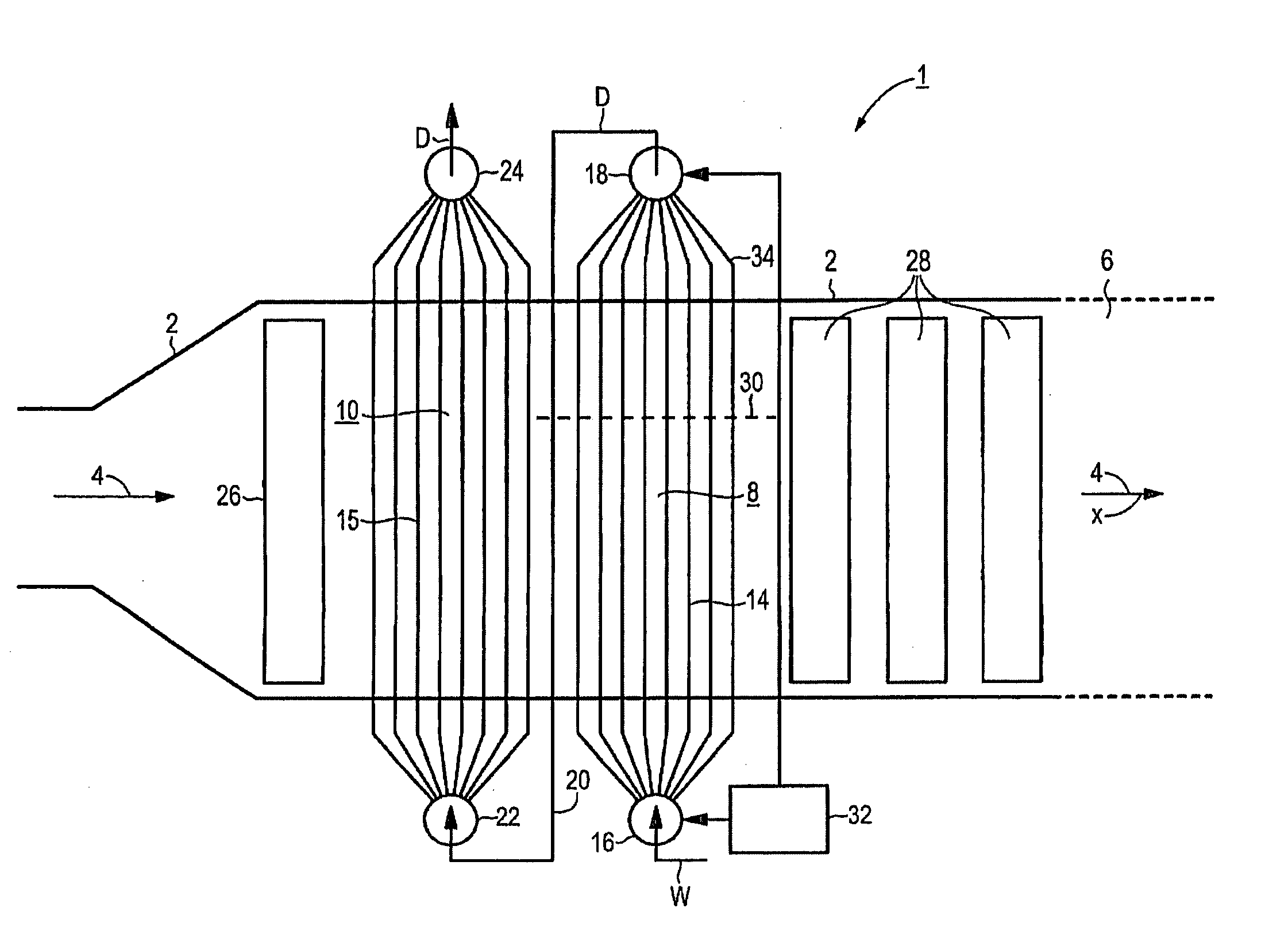
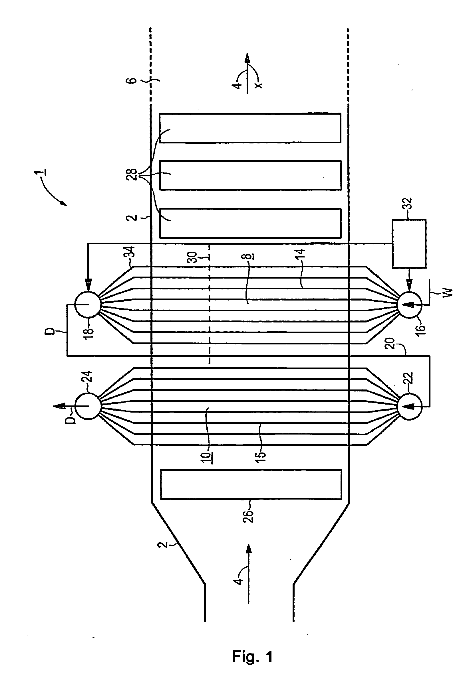
[0020] The steam generator 1 in accordance with the illustration is connected to the outlet gas end of a gas turbine (not illustrated in more detail) as a waste-heat steam generator. The steam generator 1 has a surrounding wall 2 that forms an almost horizontal heating gas channel 6 for the exhaust gas from the gas turbine, that can be traversed in the heating gas direction x shown by the arrow 4. The heating gas channel 6 contains a number of evaporator heating surfaces designed according to the continuous principle, also designated a continuous heating surface 8, 10. The exemplary embodiment shows two continuous heating surfaces 8, 10, but also just one or a greater number of continuous heating surfaces can be provided.

[0021] The continuous heating surfaces 8, 10 of the steam generator 1 each consist of a number of parallel evaporator tubes 14 or 15 in the form of a tube bundle to allow the passage of a flow medium W. The evaporator tubes 14, 15 are in this case each aligned almo...


PUM


Abstract

The invention relates to a steam generator comprising a heating gas channel, which can be traversed in an approximately horizontal heating gas direction and in which at least one continuous heating surface is located, configured from a number of approximately vertical evaporator tubes, connected in parallel to allow the passage of a flow medium. The aim of the invention is to provide a method for starting a generator, which guarantees a high degree of operational safety, even for a steam generator with a particularly simple construction. According to the invention, to achieve this, at least several evaporator tubes are partially filled to a predeterminable desired level with unevaporated flow medium, prior to the impingement of the heating gas channel by a heating gas.

Description

CROSS REFERENCE TO RELATED APPLICATIONS [0001] This application is the US National Stage of International Application No. PCT / EP02 / 09312, filed Aug. 20, 2002 and claims the benefit thereof. The International Application claims the benefits of European application No. 01121027.5 EP filed Aug. 31, 2001, both of the applications are incorporated by reference herein in their entirety.FIELD OF INVENTION [0002] The invention relates to a method for starting a steam generator with a heating gas channel that can be traversed in an almost horizontal heating gas direction, in which at least one continuous heating surface is located, configured from a number of approximately vertical evaporator tubes, connected in parallel to allow the passage of a flow medium. It also refers to a steam generator of this kind. BACKGROUND OF INVENTION [0003] In a gas and steam turbine system, the heat contained in the expanded operating medium or heating gas from the gas turbine is used to generate steam for th...

Claims


Application Information

Patent Timeline
Patent Type & Authority Applications(United States)
IPC IPC(8): F24D1/00F22B1/00F22B1/18F22B21/00F22B35/14
CPCF22B1/1815F22B35/14
Inventor FRANKE, JOACHIMKRAL, RUDOLF
Owner SIEMENS ENERGY GLOBAL GMBH & CO KG
Why Eureka
Try Eureka