Device for retaining panels

Inactive Publication Date: 2006-09-07
BROMER
View PDF6 Cites 50 Cited by
  • Summary
  • Abstract
  • Description
  • Claims
  • Application Information

AI Technical Summary

Benefits of technology

[0008] It is a further aim of the present invention to provide a rack for storing pan

Problems solved by technology

Because the panels are leaning one against another, getting access to the panels placed at the rear generally involves moving all the panels in front, which increases manipulation time and effort as w

Method used


Image

  • Device for retaining panels
  • Device for retaining panels
  • Device for retaining panels

Examples


Example

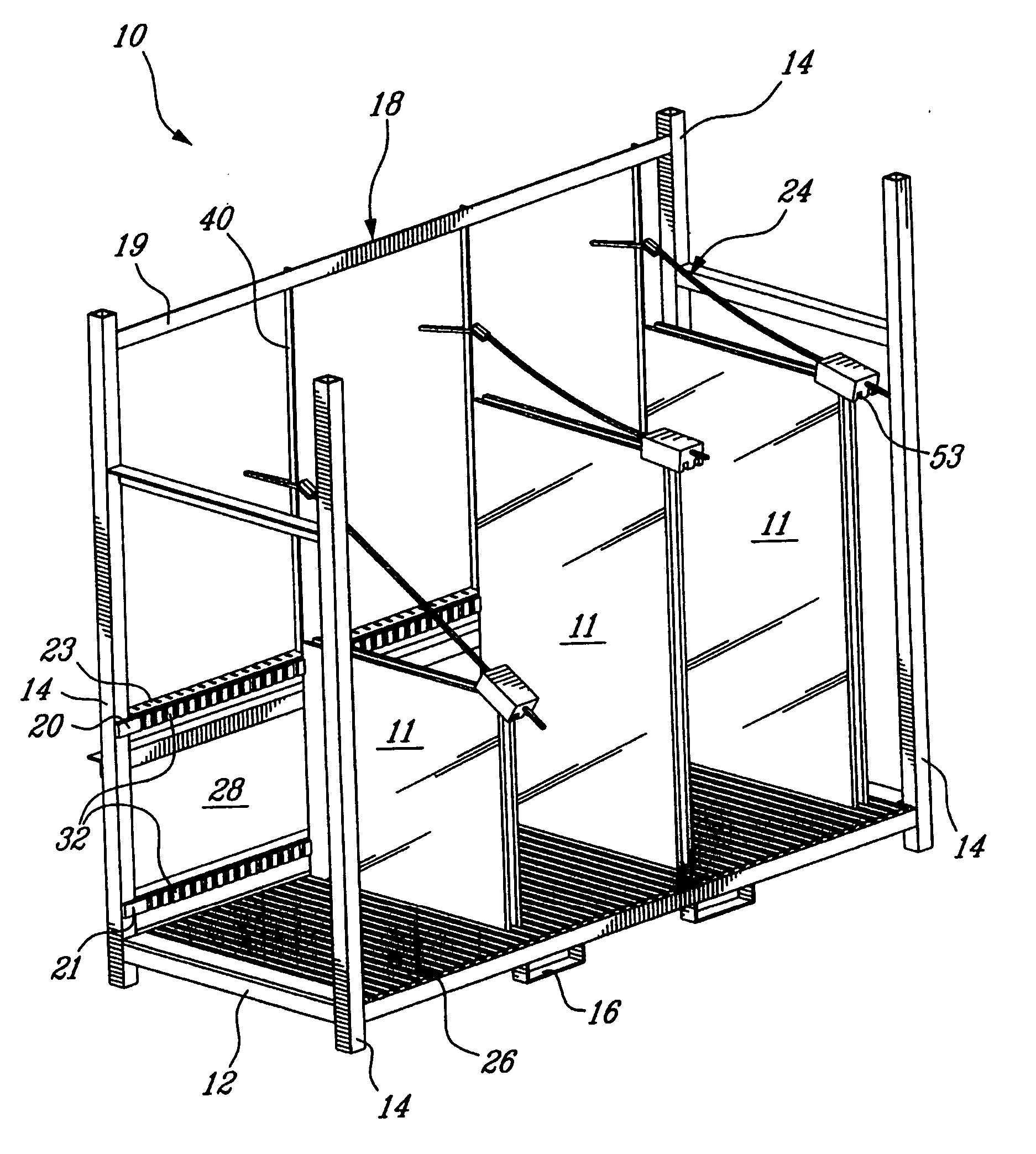
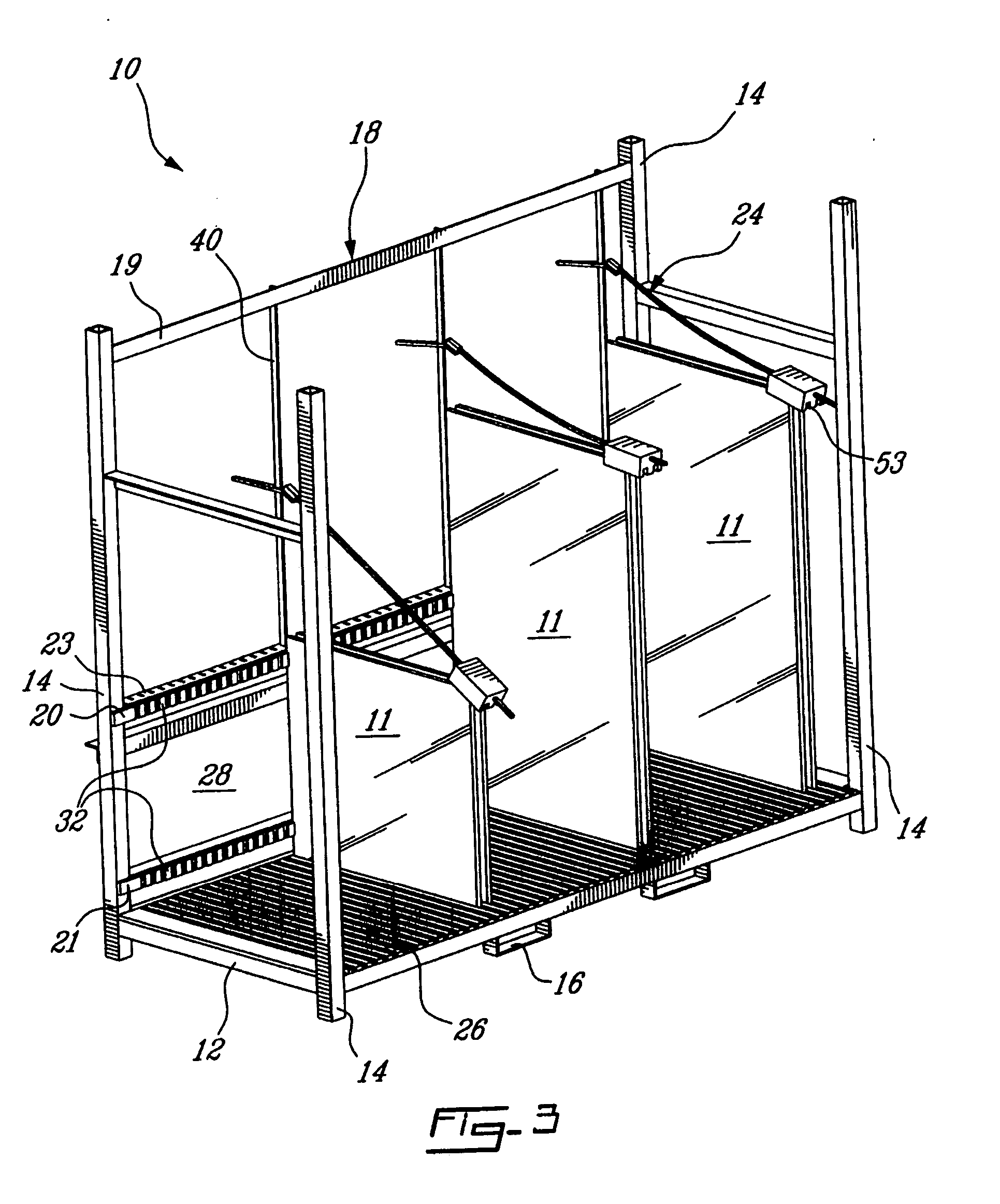
[0019] The present invention is an improvement of the rack disclosed in U.S. application Ser. No. 10 / 798,452 filed Mar. 12, 2004 by the applicants of the present application, which is incorporated herein by reference.

[0020] Referring to FIG. 3, a preferred embodiment of a rack for holding panels 11 such as glass sheets or sealed glass panel units is generally indicated at 10. The rack 10 comprises a base 12 supported by four (4) vertical posts 14. The vertical posts 14 are preferably tubular members having a square cross-section. Loop members 16 are provided under the base 12 to be engaged by a fork of a lift truck such as to ease the handling of the rack 10. Two (2) of the vertical posts 14, located at the rear side of the base 12, support a rear structure 18 extending vertically from the base 12.

[0021] The rear structure 18 comprises first, second and third horizontal bars 19,20,21 as well as a vertical plate 28, which all extend between the rear vertical posts 14. The horizonta...


PUM


Abstract

A rack for storing at least one panel, comprising a base having a top surface, a rear structure vertically extending from the base, at least one support in at least one of the top surface of the base and the rear structure for supporting the panel in a vertical position, and at least one arm including a connecting member connecting the arm to the rear structure, a retaining member engaging a top edge of the panel to retain the panel in the vertical position, and a flexible portion between the connecting member and the retaining member. A method using the rack defined hereinbefore. Said improved rack and method allow easy access to a desired panel.

Description

BACKGROUND OF THE INVENTION [0001] 1. Field of the Invention [0002] The present invention relates to cases or racks for storing panels, particularly glass panels. The invention also relates to a method for storing said panels. [0003] 2. Background Art [0004] Racks for glass panels usually receive the panels leaning against one another in a near-vertical fashion. FIG. 1 illustrates an A-frame and FIG. 2 a L-frame, both of which are well known. When these frames are used with different sized panels, the larger panels are usually placed first against the frame, with progressively smaller panels in front. Because the panels are leaning one against another, getting access to the panels placed at the rear generally involves moving all the panels in front, which increases manipulation time and effort as well as the risk of damaging one or several panels. [0005] U.S. application Ser. No. 10 / 798,452 filed Mar. 12, 2004 by the applicants of the present application discloses a rack for holding...

Claims


Application Information

Patent Timeline
IPC IPC(8): A47G19/08
CPCA47F7/0042B65D85/48B65G49/062E06B3/67365
Inventor MERCURE, ROGERRAYNAULD, ROGER
Owner BROMER
Why Eureka
Try Eureka