Check patentability & draft patents in minutes with Patsnap Eureka AI!

Paper feeder for image forming device, image forming device, storage medium for paper feeder control program, and paper feeder control method

a technology of paper feeder and paper feeder, which is applied in the direction of thin material processing, article separation, transportation and packaging, etc., can solve the problems of paper jam, insufficient results, and determination of paper jam, so as to improve paper feeding performance and suppress misfeeds

Inactive Publication Date: 2006-09-07
KYOCERA DOCUMENT SOLUTIONS INC
View PDF13 Cites 2 Cited by
  • Summary
  • Abstract
  • Description
  • Claims
  • Application Information

AI Technical Summary

Benefits of technology

[0009] An object of the present invention is to suppress misfeeds while feeding paper in an image forming device and to improve paper feeding performance.
[0011] With this device, when paper is placed on the paper placing unit the flapper will move up and down at least one time prior to feeding paper so that the paper will flow smoothly on the flapper, and therefore paper feeding performance will be improved and the occurrence of paper jams can be reduced.
[0016] With this device, the paper can be more smoothly fed if the flapper is made to move up and down immediately before the paper is fed.
[0019] With this device, the retry control will effectively function because the paper is fed smoothly because the flapper is moved prior to the retry control.
[0024] With this device, when paper is placed on the paper placing unit, the flapper will move up and down at least one time prior to feeding paper, so the paper on the flapper will move smoothly, and therefore paper feeding performance can be improved and the occurrence of paper jams can be reduced.
[0027] With the present invention, when paper is placed on the paper placing unit, the flapper moves up and down at least one time prior to the paper being fed, so the paper on the flapper will move smoothly, and therefore paper feeding performance can be improved, and the occurrence of paper jams can be reduced.

Problems solved by technology

Furthermore, with this technology, if misfeeding continues to occur even though retry control has been performed more than a predetermined number of times, a paper jam will be determined to have occurred.
However, even with this type of retry control, the paper feeder roller may slip and cause a paper jam when the paper is fed again even if the paper feeder roller is stopped or the speed is changed or the like, and thus at times sufficient results are not obtained.

Method used


Image

  • Paper feeder for image forming device, image forming device, storage medium for paper feeder control program, and paper feeder control method
  • Paper feeder for image forming device, image forming device, storage medium for paper feeder control program, and paper feeder control method
  • Paper feeder for image forming device, image forming device, storage medium for paper feeder control program, and paper feeder control method

Examples


Embodiment Construction

[0036] Construction of Image Forming Device

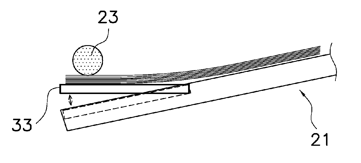
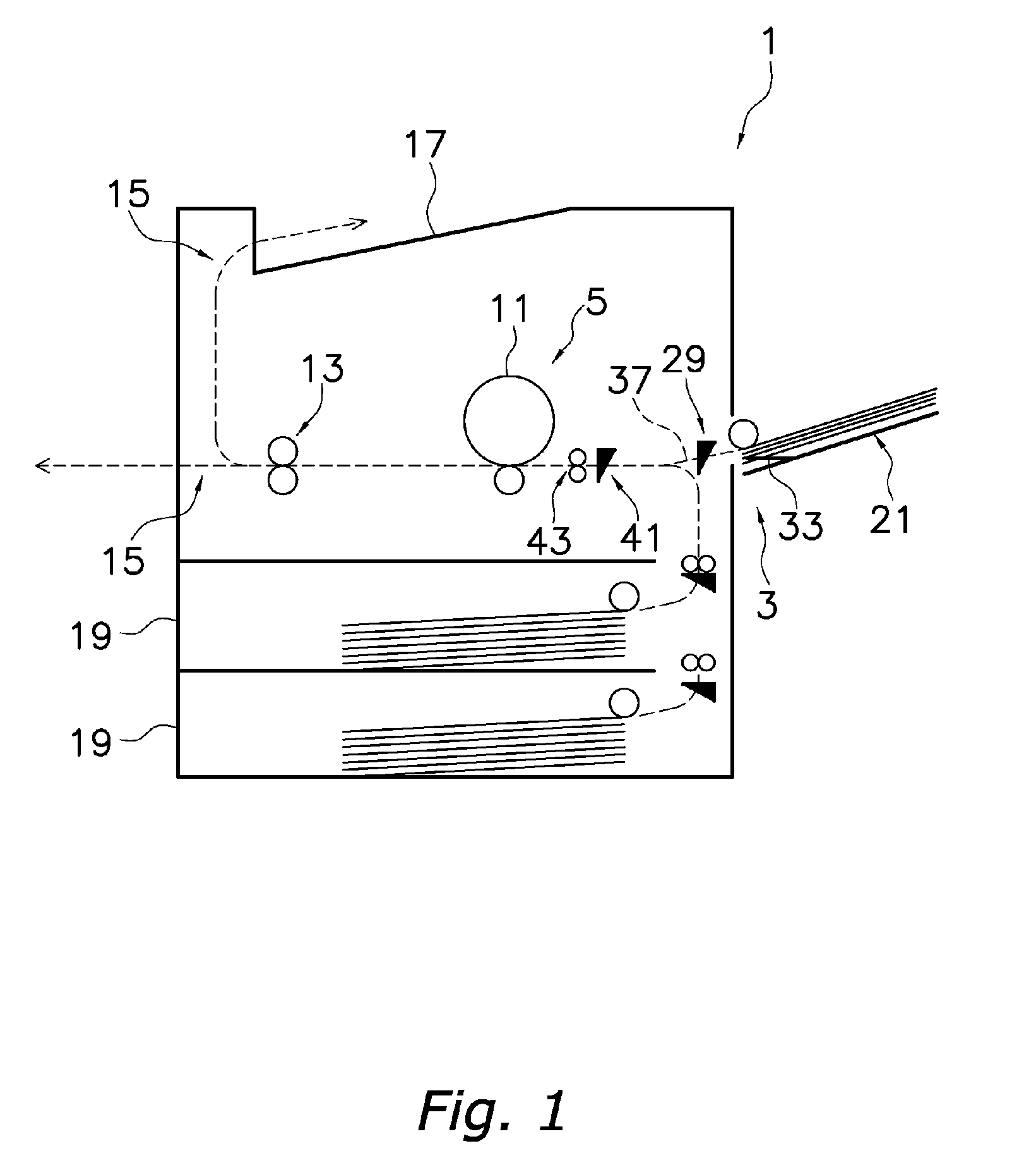
[0037] A color printer is shown in FIG. 1 and FIG. 2 as an image forming device which uses an embodiment of the present invention.

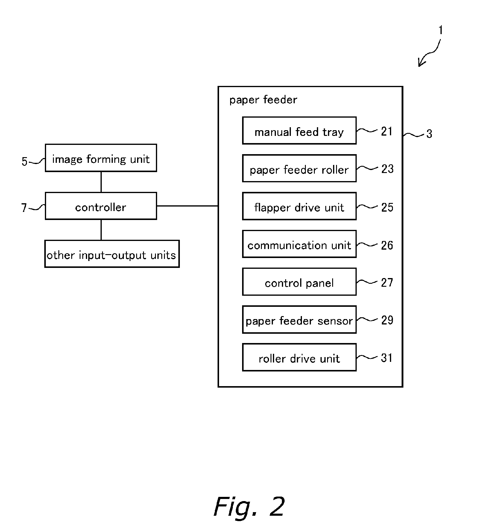
[0038] A printer comprises a paper feeder 3, an image forming unit 5, a control unit 7, and other input-output units.

[0039] The image forming unit 5 is for forming an image on paper fed from the paper feeder 3 or a paper feeder cassette 19, and has a photosensitive drum 11, developing devices for each of the toner colors, cyan, magenta, and yellow, located in close proximity, and a toner cartridge (all not shown in the figures), and a fixing device 13 located downstream thereof. Incidentally, a resist sensor 41 and a resist roller 43 are located upstream from the image forming unit 5.

[0040] The control unit 7 performs image processing and controls the operation of the input-output units such as the image forming unit 5, and comprises a microcomputer which includes CPU and memory. Various programs for running ...


PUM


Abstract

A paper feeder of a printer 1 includes a manual feed tray 21, a paper feeder roller 23, and a flapper drive unit 25. The manual feed tray 21 has a flapper 33 which can move up and down in the paper stacking direction. The paper feeder roller 23 is located above the manual feed tray 21, and is able to feed the paper on the flapper 33. The flapper drive unit 25 can move the flapper 33 up and down in the paper stacking direction to contact the paper feeder roller 23 through the paper, and moves the flapper 33 up and down at least from the moment that the paper is placed in the manual feed tray 21 until the paper is fed by the paper feeder roller 23.

Description

BACKGROUND OF THE INVENTION [0001] 1. Field of the Invention [0002] The present invention relates to a paper feeder for an image forming device, an image forming device, a storage medium for a paper feeder control program, and a paper feeder control method. [0003] 2. Background Information [0004] Image forming devices such as copiers and printers or the like are commonly known which for instance have a flapper which can move up and down in the paper stacking direction in a manual feed tray. In these types of devices, a space between the flapper and a paper feeder roller positioned thereabove is formed by lowering the flapper, so documents with many pages can easily be set. [0005] Conventional image forming device are also known which, if a misfeed occurs where paper is not detected by a sensor when paper is fed from either the manual feed tray or a paper feeder cassette, the paper feeder rotation drive will be momentarily stopped and then started again, or the rotation speed of the ...

Claims


Application Information

Patent Timeline
Patent Type & Authority Applications(United States)
IPC IPC(8): B65H1/08
CPCB65H1/14B65H3/0607B65H2403/512B65H2405/11162B65H2511/51B65H2511/515B65H2511/528B65H2220/01B65H2220/02
Inventor YAMASHITA, HIROSHINAKAHAMA, TAKAYUKI
Owner KYOCERA DOCUMENT SOLUTIONS INC
Features
  • R&D
  • Intellectual Property
  • Life Sciences
  • Materials
  • Tech Scout
  • Unparalleled Data Quality
  • Higher Quality Content
  • 60% Fewer Hallucinations
Learn More