Method of assuming acting point of floor reaction force to biped walking mobile body and method of assuming joint moment of biped walking mobile body

a technology of biped walking and reaction force, which is applied in the direction of distance measurement, programme control, instruments, etc., can solve the problems of inconvenient use, inability to apply the technique to the walking of a and inability to grasp the moment of action on the legs of the biped walking mobile body in a normal environment. , to achieve the effect of simple arithmetic processing

Inactive Publication Date: 2006-09-07
HONDA MOTOR CO LTD
View PDF6 Cites 21 Cited by
  • Summary
  • Abstract
  • Description
  • Claims
  • Application Information

AI Technical Summary

Benefits of technology

[0030] The joint moment estimating method in accordance with the present invention makes it possible to estimate, in real-time, the moment acting on a joint of a leg by relatively simple arithmetic processing by using the position of the floor reaction force acting point estimated according to the floor reaction force acting point estimating method in accordance with the present invention described above so as to estimate the moment acting on a joint of a leg, thus obviating the need for preparing multiple types of correlation data beforehand or for attaching a relatively large sensor to a biped walking mobile body.

Problems solved by technology

According to this technique, however, the positions of floor reaction force acting points cannot be grasped, making the technique inadequate for grasping moments acting on the joints of legs of the biped walking mobile body.
This technique, however, presents a problem in that the floor reaction forces and the positions of floor reaction force acting points can be grasped only in an environment wherein a force plate is installed, so that the technique cannot be applied to the walking of a biped walking mobile body in a normal environment.
This has been inconveniently taking up a major part of the capacity of the memory.
There has been another inconvenience in that, when a motion mode is changed over, discontinuity in position of a floor reaction force acting point estimated on the basis of another correlation data before or after the changeover is likely to occur, resulting in a discontinuously changed estimated value of a joint moment when the estimated position of the floor reaction force acting point is used to estimate the joint moment.

Method used


Image

  • Method of assuming acting point of floor reaction force to biped walking mobile body and method of assuming joint moment of biped walking mobile body
  • Method of assuming acting point of floor reaction force to biped walking mobile body and method of assuming joint moment of biped walking mobile body
  • Method of assuming acting point of floor reaction force to biped walking mobile body and method of assuming joint moment of biped walking mobile body

Examples


first embodiment

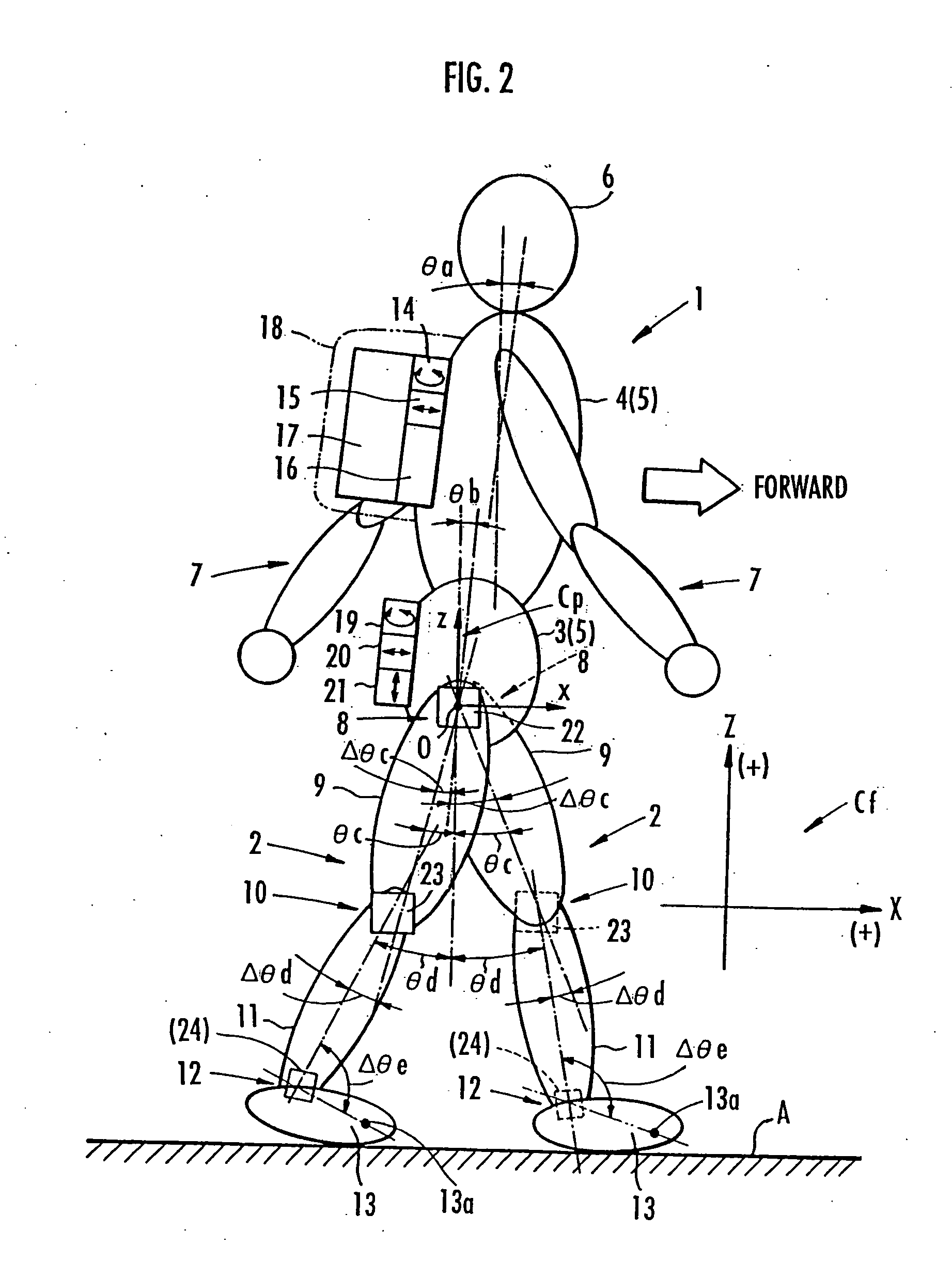
[0058] The first embodiment in which the present invention has been applied to a human being as a biped walking mobile body will now be explained in detail.

[0059] As schematically shown in FIG. 2, a human being 1 is roughly constructed of a pair of right and left legs 2, 2, a torso 5 composed of a waist 3 and a chest 4, a head 6, and a pair of right and left arms 7, 7. In the torso 5, the waist 3 is connected to the legs 2, 2 through the intermediary of a pair of right and left hip joints 8, 8, and is supported on the two legs 2, 2. The chest 4 of the torso 5 exists above the waist 3 such that it can be tilted toward the front of the human being 1 with respect to the waist 3. And the arms 7, 7 are provided such that they extend from right and left sides of the upper part of the chest 4, and the head 6 is supported on the upper end of the chest 4.

[0060] Each leg 2 has a thigh 9 extending from the hip joint 8 and a crus 11 extending from the distal end of the thigh 9 through the inte...

second embodiment

[0070] The arithmetic processing unit 16 is equipped with the functional means shown in FIG. 3. In FIG. 3, the parenthesized portion (the portion of the ankle joint angle sensor 24) and the portion enclosed by the chain double-dashed line are related to the second embodiment to be discussed later, and these parenthesized portion and the portion enclosed by the chain double-dashed line are unnecessary. Therefore, in the following explanation of the arithmetic processing unit 16 in the present embodiment, nothing related to these parenthesized portion and the portion enclosed by the chain double-dashed line will be referred to.

[0071] As shown in FIG. 3, the arithmetic processing unit 16 in the present embodiment is equipped with a leg motion determining means 25 that uses the detection data of the waist vertical acceleration sensor 21 and the data on an estimated value of a floor reaction force of each leg 2 determined by a floor reaction force estimating means 38, which will be discu...


PUM


Abstract

While a biped walking mobile body is in a motion, including level-ground walking, the position of the center of gravity (G0) of the biped walking mobile body, the position of an ankle joint (12) of each leg (2), and the position of a metatarsophalangeal joint (13a) of a foot (13) are successively grasped, and the horizontal position of a floor reaction force acting point of the leg (2) in contact with the ground is estimated on the basis of the relative positional relationship among the aforesaid positions. Depending on whether the center of gravity (G0) is behind the ankle joint (12), between the ankle joint (12) and the metatarsophalangeal joint (13a), or before the metatarsophalangeal joint (13a) with respect to the advancing direction of the biped walking mobile body, the horizontal position of the ankle joint (12), the center of gravity (G0), or the metatarsophalangeal joint (13a) is defined as the horizontal position of a floor reaction force acting point. The vertical position of the floor reaction force acting point is estimated on the basis of the vertical distance from the ankle joint (12) to a ground contact surface.

Description

TECHNICAL FIELD [0001] The present invention relates to a method of estimating the position of a floor reaction force acting point of each leg of a biped walking mobile body, such as a human being or a biped walking robot. The present invention further relates to a method of estimating the moment acting on a joint of a leg of a biped walking mobile body by using an estimated value of the position of the floor reaction force acting point. BACKGROUND ART [0002] To control an operation of, for example, a walking aid apparatus for assisting a human being in walking or to control a traveling motion of a biped walking robot, it is necessary to successively grasp the floor reaction forces acting on legs of the human being or the biped walking robot (to be more specific, the forces from a floor that act on ground contact portions of the legs) and the positions of floor reaction force acting points. Grasping the floor reaction forces and the floor reaction force acting points makes it possib...

Claims


Application Information

Patent Timeline
Patent Type & Authority Applications(United States)
IPC IPC(8): B25J5/00B62D57/032
CPCB62D57/032
Inventor KAWAI, MASAKAZU
Owner HONDA MOTOR CO LTD
Why Eureka
Try Eureka