
Check device

An inspection device and inspection object technology, applied in measurement devices, optical testing flaws/defects, instruments, etc., can solve problems such as complex computing and processing

Active Publication Date: 2022-05-06
NIDEC TOSOK CORP
View PDF5 Cites 0 Cited by
  • Summary
  • Abstract
  • Description
  • Claims
  • Application Information

AI Technical Summary

Problems solved by technology

Therefore, arithmetic processing for defect inspection sometimes becomes complicated

Method used


Image

  • Check device
  • Check device
  • Check device

Examples


Embodiment Construction

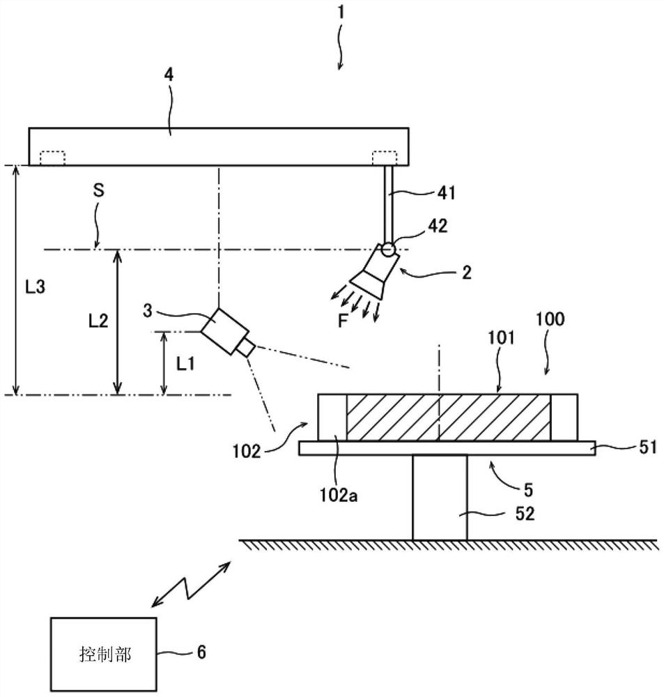
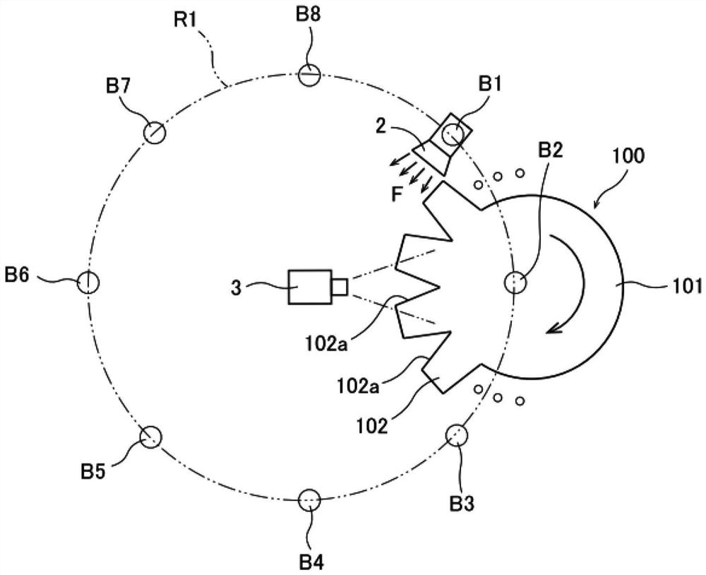
[0021] Next, exemplary embodiments of the inspection device and inspection method of the present invention will be described with reference to the drawings. The inspection device and inspection method of the present invention are devices and methods for performing visual inspection of a surface to be inspected included in an outer peripheral surface of an object to be inspected. Hereinafter, the direction parallel to the thickness direction and axis of the object to be inspected is called "axial direction", and the direction perpendicular to the axial direction is called "radial direction". The direction of is called "circumferential direction" for illustration.

[0022]

[0023] The inspection device 1 of the present embodiment automatically performs an appearance inspection for detecting defects such as dents on the surface of an inspection object 100 having a thickness in the axial direction. More specifically, the inspection object 100 of the present embodiment has a ma...


PUM


Abstract

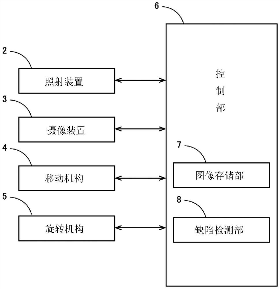
An inspection device is provided. This inspection apparatus is an apparatus that performs an appearance inspection of the surface to be inspected included in the object to be inspected. This inspection device includes an irradiation device, an imaging device, an image storage unit, and a defect detection unit. The irradiation device moves on an imaginary plane along the surface of the object to be inspected, and irradiates light toward the surface to be inspected of the object to be inspected. The imaging device includes the inspection surface of the inspection object in the imaging range, receives light reflected by the inspection surface, and generates a luminance distribution image as an imaging result. The image storage unit stores a plurality of luminance distribution images captured by the imaging device at a plurality of timings when the positions of the irradiation devices are different and the surface to be inspected, the imaging device and the irradiation device are not aligned in a straight line. The defect detection unit detects defects on the surface to be inspected based on a plurality of different luminance distribution images.

Description

technical field [0001] The present invention relates to inspection devices. Background technique [0002] Conventionally, there are known inspection devices used to automatically inspect whether or not there is a defect such as a dent on an inspection surface of an inspection object. Such an inspection device is disclosed in, for example, Japanese Patent Application Laid-Open No. 2007-33236. [0003] The surface defect inspection device described in Japanese Patent Application Laid-Open No. 2007-33236 is composed of an illumination unit, an imaging unit, a light source control device, and a defect inspection device. The lighting unit is composed of a plurality of light sources (1a-1f) arranged in sequence on a curved surface. The plurality of imaging units are composed of a plurality of imaging devices (2a to 2f) arranged sequentially on the curved surface. A light source control device (4) selects one light source from among a plurality of light sources in the lighting u...

Claims


Application Information

Patent Timeline
Patent Type & Authority Patents(China)
IPC IPC(8): G01N21/88
CPCG01N21/88G01N21/8806G01N21/8851G01N2021/8838G01N2021/8893G01N2201/061G01N2201/102
Inventor 野村昭农宗千典
Owner NIDEC TOSOK CORP
Learn More