Die feeder

A technology for supplying devices and bare chips, applied in electrical components, semiconductor/solid-state device manufacturing, circuits, etc., can solve problems such as adsorption of qualified bare chips, and achieve the effect of simplifying computing processing

Active Publication Date: 2017-10-03
FUJI KK
View PDF9 Cites 0 Cited by
  • Summary
  • Abstract
  • Description
  • Claims
  • Application Information

AI Technical Summary

Problems solved by technology

As a result, the acceptable die 31 may not be picked up in the correct order, or the bad die A or the area without a die may be mistakenly estimated as the next pick-up die and photographed, causing problems.

Method used


Image

  • Die feeder
  • Die feeder
  • Die feeder

Examples


Embodiment Construction

[0023] Hereinafter, an example which actualizes the embodiment for carrying out the present invention will be described.

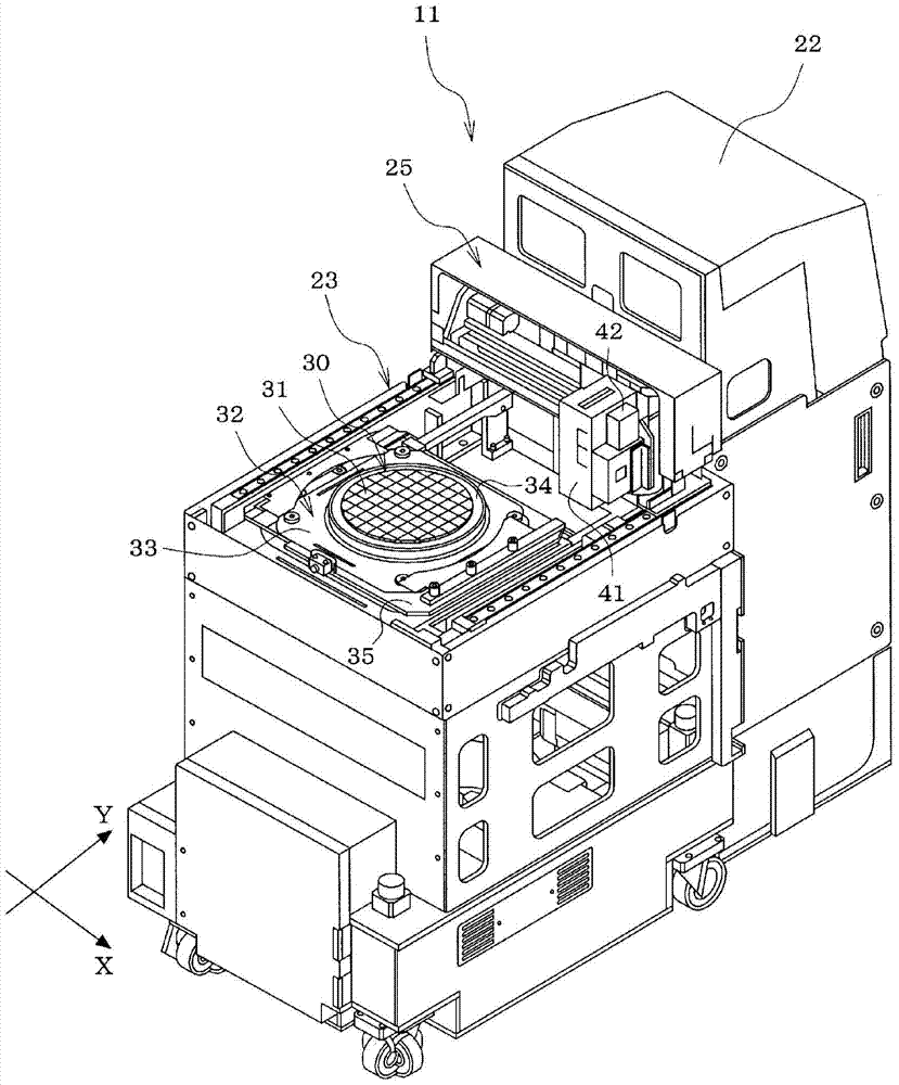
[0024] First, use figure 1 , the structure of the die supply device 11 is schematically described.

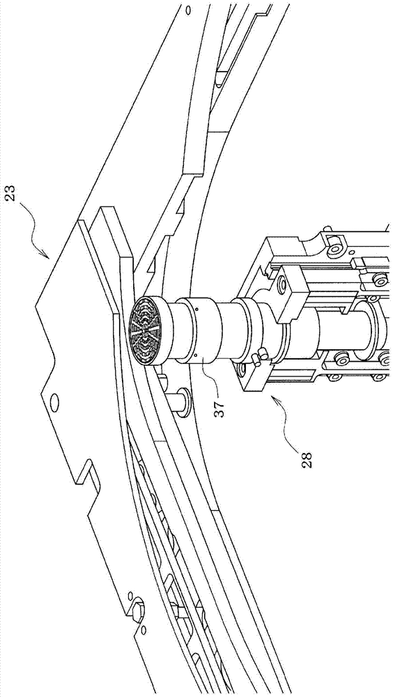
[0025] The die supply device 11 is provided with a magazine holding unit 22 (tray tower), a tray pull-out table 23, an XY moving mechanism 25, and a jacking unit 28 (refer to figure 2 ), etc., and set the tray pull-out table 23 in a state inserted into a component mounting machine (not shown).

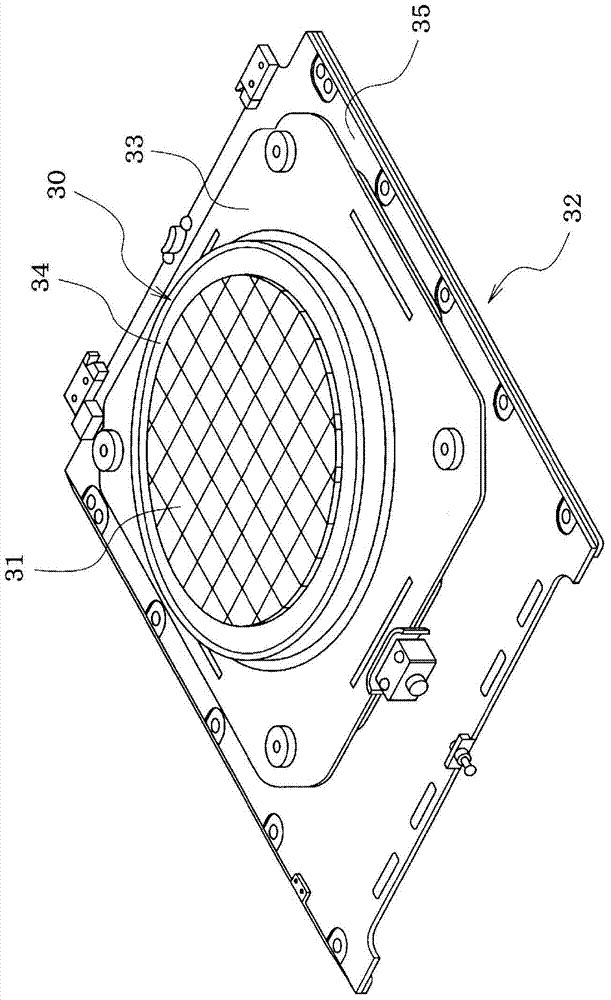
[0026] In the magazine (not shown) accommodated in the magazine holding part 22 of the die supply device 11 in a manner capable of moving up and down, the wafer tray 32 on which the wafer spreader 30 is mounted is loaded in multiple layers, and the wafer tray 32 is loaded in multiple layers during production. The magazine pulls the wafer tray 32 out onto the tray pullout station 23 . Such as image 3As shown, the wafer stretching body 30 is installed on a cutt...


PUM


Abstract

When a plurality of image-recognizable fiducial dies 45 are disposed at predetermined intervals in an arrangement of dies 31 on a dicing sheet 34, and an interval from a position of a die 31(a) which is subjected to a present adsorption operation to an estimated position for a next adsorption die 31(b) is equal to or greater than a predetermined value, in addition to recognizing the position for the next adsorption die 31(b), a fiducial die 45 adjacent to the next adsorption die 31(b) is selected from the plurality of fiducial dies 45, the fiducial die 45 is imaged by a camera 42, a position of the fiducial die 45 is recognized, and it is determined whether or not a recognition position for the next adsorption die 31 (b) is a proper position for a next adsorption die 31 (c) based on a positional relationship between a recognition position of the fiducial die 45 and the recognition position for the next adsorption die 31(b). When it is determined that the recognition position for the next adsorption die 31 (b) is not the proper position for the next adsorption die 31(c), the position of the die 31(c) to be adsorbed next is reestimated based on the recognition position of the fiducial die 45, the die 31(c) is imaged by the camera 42, the position of the die 31(c) is recognized, and push-up operation and adsorption operation are executed.

Description

technical field [0001] The present invention relates to a die supply device for supplying bare chips from a wafer spreader in which stretchable dicing sheets to which wafers to be diced are pasted are stretched. Background technique [0002] In recent years, as described in Patent Document 1 (Japanese Unexamined Patent Publication No. 2010-129949 ), a die supply device for supplying die is provided on a component mounting machine, and the die is mounted on a circuit board by the component mounting machine. This die supply device includes: a wafer tray formed by stretching a stretchable dicing sheet on a dicing frame to which a wafer to be diced to be divided into a plurality of dies is pasted; and a top disposed below the dicing sheet. Lifting pin, when the suction nozzle is lowered to absorb and pick up the die on the above-mentioned cutting sheet, the sticking part of the die to be adsorbed in the cutting sheet is lifted by the lifting pin, so that the sticking part of the...

Claims


Application Information

Patent Timeline
Patent Type & Authority Patents(China)
IPC IPC(8): H05K13/02H01L21/68
CPCH01L21/67132H01L21/67259H01L21/681H05K13/043
Inventor 柘植邦明贵岛达也山下义哲
Owner FUJI KK
Why Eureka
Try Eureka