Communication apparatus

a technology of communication apparatus and communication channel, applied in the field of communication channel, can solve problems such as packet congestion, severe damage, and packet congestion, and achieve the effect of preventing the transmission of broadcast storms

Inactive Publication Date: 2006-09-07
FUJITSU LTD
View PDF4 Cites 68 Cited by
  • Summary
  • Abstract
  • Description
  • Claims
  • Application Information

AI Technical Summary

Problems solved by technology

If a network failure occurs in such a carrier network and a recovery delays, severe damage arises.
Even when many redundant structures are used, they are meaningless unless the apparatus can detect a failure quickly and correctly.
If a silent failure (failure where automatic switching to a redundant system is not performed, no alarm is issued to the operator, and it is difficult to recognize that a malfunction occurs) occurs, a failure period is extended, and in an Ethernet network, a loop may be generated to cause packet congestion.
This is because, if a loop-shaped path is formed in the network, packet congestion called a broadcast storm occurs when a packet is broadcast.
. . eternally, causing congestion.
Otherwise, the service is not available for a long period of time.
Since the current network-failure detection which uses a vendor-unique protocol requires control with the monitoring contents of the opposite apparatus being taken into account, as described above, however, the detection can only apply to links connected between apparatuses made by an identical vendor in a network.
Therefore, it is not convenient for the current multivendor carrier networks to use this network-failure detection.
In addition, the standardization of a protocol for detecting a network failure has not yet advanced.

Method used


Image

  • Communication apparatus
  • Communication apparatus
  • Communication apparatus

Examples


first embodiment

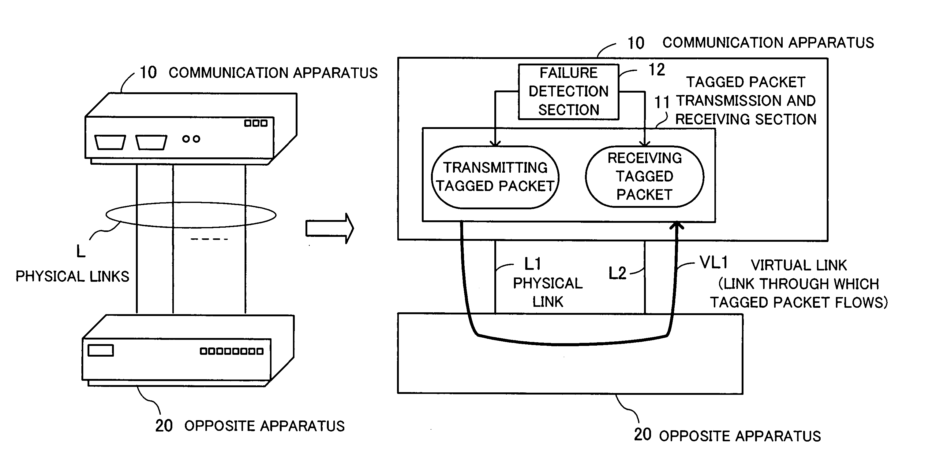
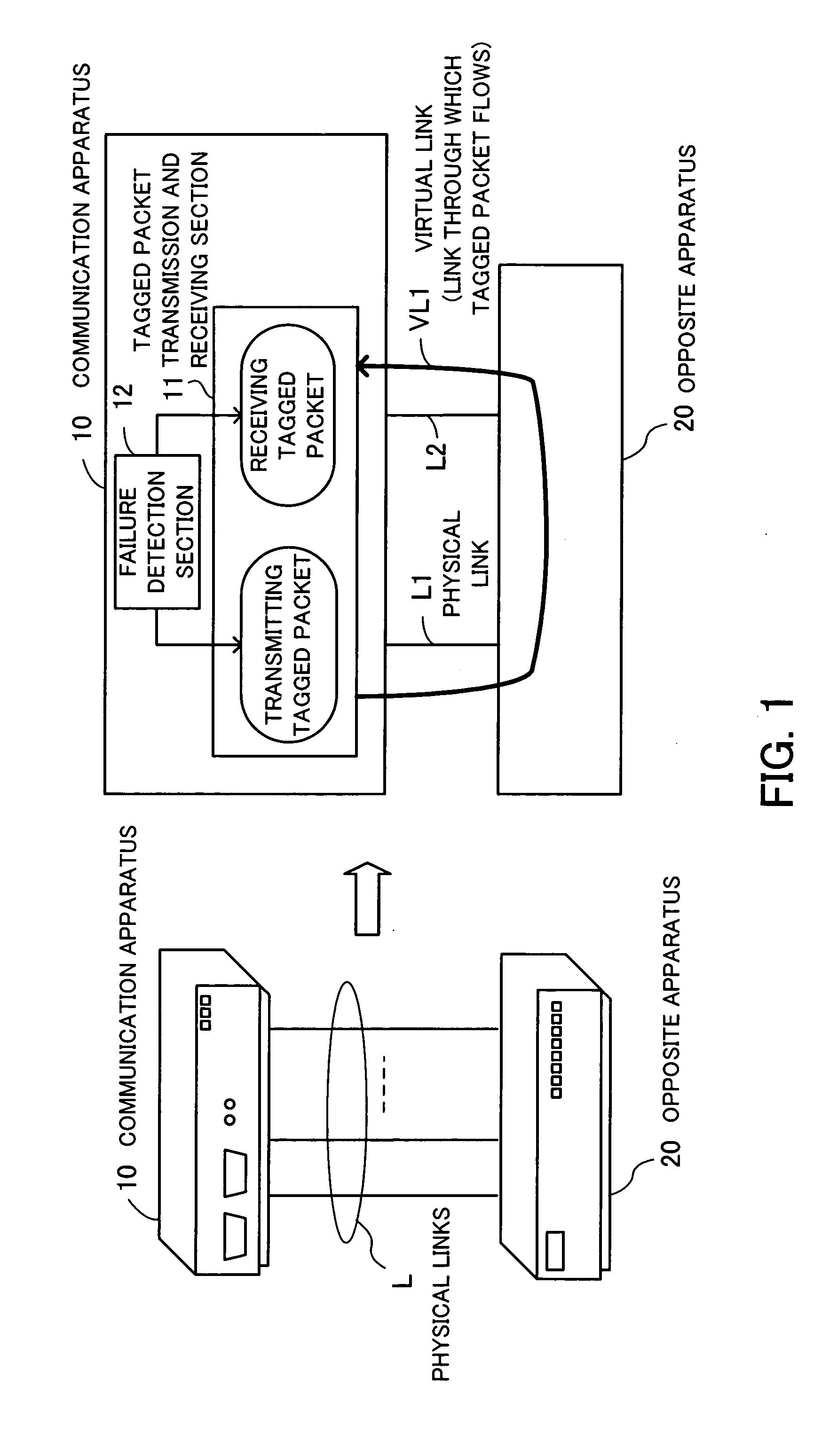
[0058] The operation of the communication apparatus 10 will be next described in detail. To make the following description easy to understand, the tagged packet transmission and receiving section 11, which has a transmission and receiving function, is divided into a tagged packet transmission section and a tagged packet receiving section. These two sections will be illustrated as separate elements. A first embodiment will be described in which failure monitoring is performed with two physical links being treated as a pair.

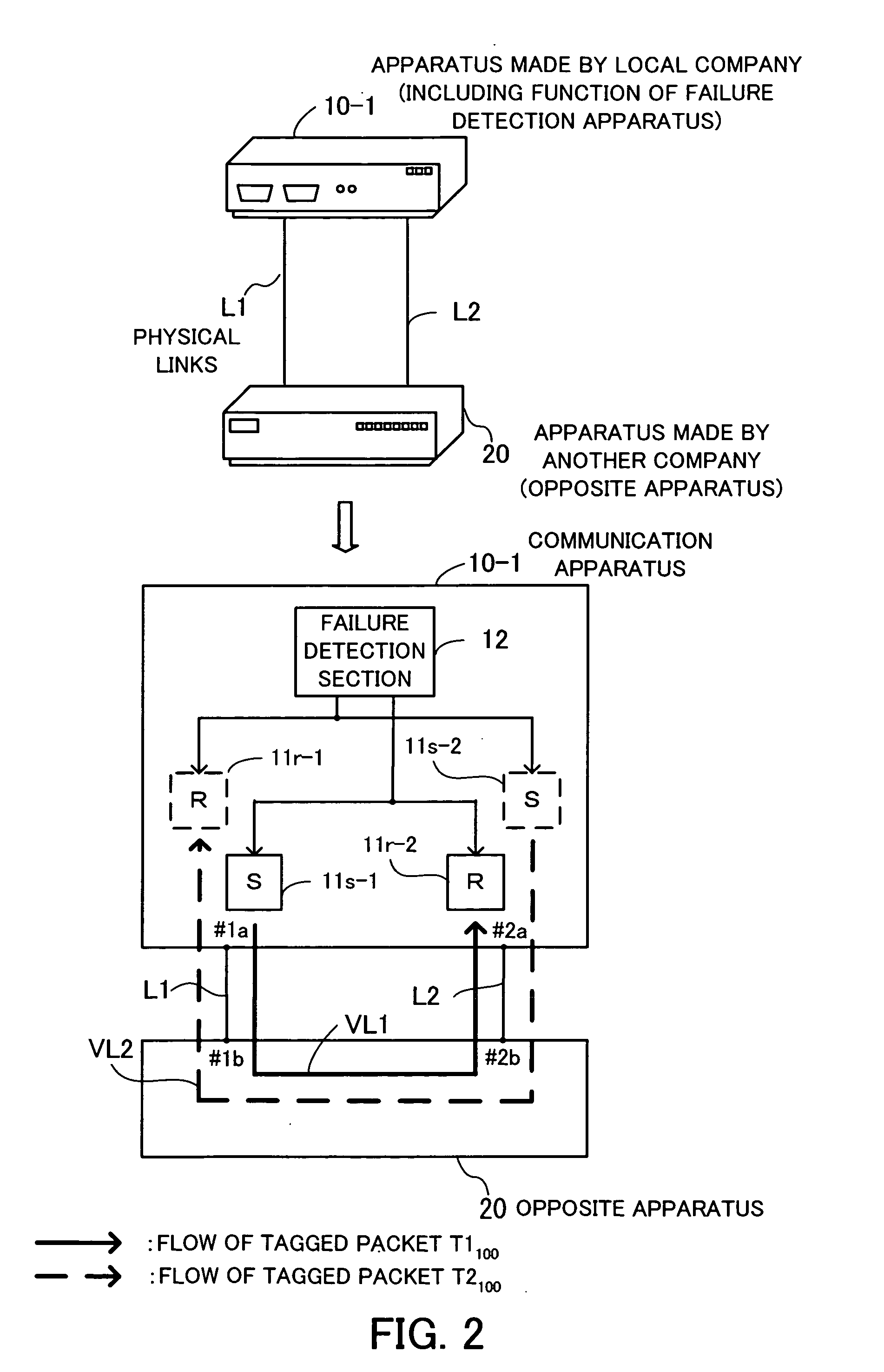
[0059]FIG. 2 is a view showing operations according to the first embodiment. A port #1a of a communication apparatus 10-1 and a port #1b of an opposite apparatus 20 are connected with a physical link L1, and a port #2a of the communication apparatus 10-1 and a port #2b of the opposite apparatus 20 are connected with a physical link L2. The physical links L1 and L2 are treated as a pair (the port #la and the port #2a are treated as a pair) and a link state is monito...

second embodiment

[0074]FIG. 3 is a view showing operations according to the A communication apparatus 10-2 and an opposite apparatus 20 are connected by four physical links L1, L2, L3, and L4. The physical link L1 connects a port #1a of the communication apparatus 10-2 and a port #1b of the opposite apparatus 20, the physical link L2 connects a port #2a of the communication apparatus 10-2 and a port #2b of the opposite apparatus 20, the physical link L3 connects a port #3a of the communication apparatus 10-2 and a port #3b of the opposite apparatus 20, and the physical link L4 connects a port #4a of the communication apparatus 10-2 and a port #4b of the opposite apparatus 20.

[0075] The physical links L1 and L2 form one LA group (called LA1), and the physical links L3 and L4 form another LA group (called LA2). Failure detection is applied to one pair of LA groups LA1 and LA2. When LA1 and LA2 are used to increase the bandwidth, communications with the use of LA1 and LA2 between the apparatuses are p...

third embodiment

[0091]FIG. 4 is a view showing operations according to the A communication apparatus 10-3 and an opposite apparatus 20 are connected by four physical links. Among them, one link serves as a common physical link L1c, and the other links form a group of physical links L2, L3, and L4.

[0092] The common physical link L1c connects a port #1a of the communication apparatus 10-3 and a port #1b of the opposite apparatus 20, the physical link L2 connects a port #2a of the communication apparatus 10-3 and a port #2b of the opposite apparatus 20, the physical link L3 connects a port #3a of the communication apparatus 10-3 and a port #3b of the opposite apparatus 20, and the physical link L4 connects a port #4a of the communication apparatus 10-3 and a port #4b of the opposite apparatus 20.

[0093] In this type of connections, virtual links VL1, VL2, and VL3 are monitored in which packets flow from the ports #2a, #3a, and #4a through the opposite apparatus 20 (tunneling) to the port #1a, which s...


PUM


Abstract

A communication apparatus that detects a network failure by itself, without using any particular protocol to interact with other apparatuses in a multivendor virtual LAN (VLAN) environment. The communication apparatus has a group of physical link ports, including first and second ports, to provide physical link connections to an opposite apparatus. A virtual link from the first port to the second port is formed by tunneling through the opposite apparatus. A tagged packet transmission and receiving section transmits outgoing tagged packets from the first physical link port, while receiving incoming tagged packets arriving at the second physical link port. A failure detection section detects a failure on the VLAN by checking whether every tagged packet sent out of the first port can return to the second port via the virtual link that tunnels through the opposite apparatus.

Description

CROSS-REFERENCE TO RELATED APPLICATIONS [0001] This application is based upon and claims the benefits of priority from the prior Japanese Patent Application No. 2005-056892, filed on Mar. 2, 2005, the entire contents of which are incorporated herein by reference. BACKGROUND OF THE INVENTION [0002] 1. Field of the Invention [0003] The present invention relates to communication apparatuses, and particularly to a communication apparatus which detects a failure on a network. [0004] 2. Description of the Related Art [0005] Wide-area Ethernets (Ethernet is a registered trademark) have been spread recently as carrier services which use local area networks (LANs), provided by communication business parties. In the wide-area Ethernets, a plurality of Ethernet LAN environments is integrated by connecting networks with the use of layer-2 switches. [0006] Since inexpensive switching hubs (layer-2 switches) are used in the wide-area Ethernets instead of expensive routers (layer-3 switches), netw...

Claims


Application Information

Patent Timeline
Patent Type & Authority Applications(United States)
IPC IPC(8): H04J1/16H04L12/56H04B17/00H04L12/28H04L12/46H04L12/70
CPCH04L12/462H04L12/4645H04L69/40
Inventor SASAGAWA, YASUSHIKAWARAI, KENICHIDOUKAI, MASAMITAKATORI, KOU
Owner FUJITSU LTD
Why Eureka
Try Eureka