Chirped coherent laser radar system and method

Active Publication Date: 2006-09-14
AEVA INC
View PDF62 Cites 49 Cited by
  • Summary
  • Abstract
  • Description
  • Claims
  • Application Information

AI Technical Summary

Benefits of technology

[0010] One aspect of various embodiments of the invention may relate to a laser radar system that unambiguously detects a range of a target and a range rate at which the target is moving relative to the laser radar system. Another aspect of various embodiments of the invention may relate to a laser radar system that uses multiple laser radar sections to obtain multiple simultaneous measurements (or substantially

Problems solved by technology

Conventional systems are typically limited in various aspects of operation.
For example, these conventional systems are not able to provide range and/or range rate information instantaneously based on the target signal and reference signal, or unambiguously determine distance and velocity.
These conventional systems are limited in other ways as well.
These limitations may be exacerbated by various operating conditions such as, for example, target acceleration toward or away from the target interferometer, using an

Method used


Image

  • Chirped coherent laser radar system and method
  • Chirped coherent laser radar system and method
  • Chirped coherent laser radar system and method

Examples


Example

DETAILED DESCRIPTION OF THE DRAWINGS

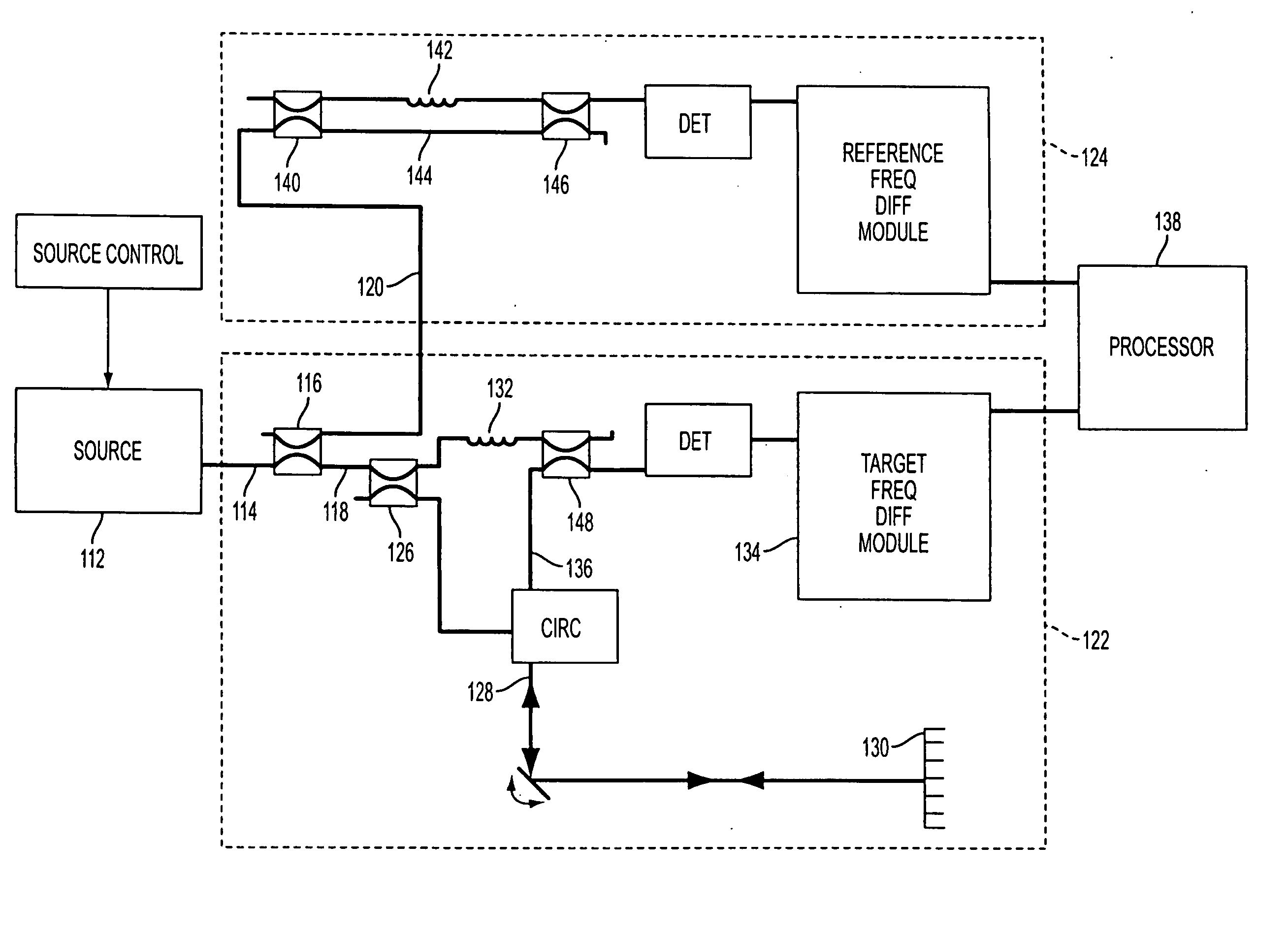
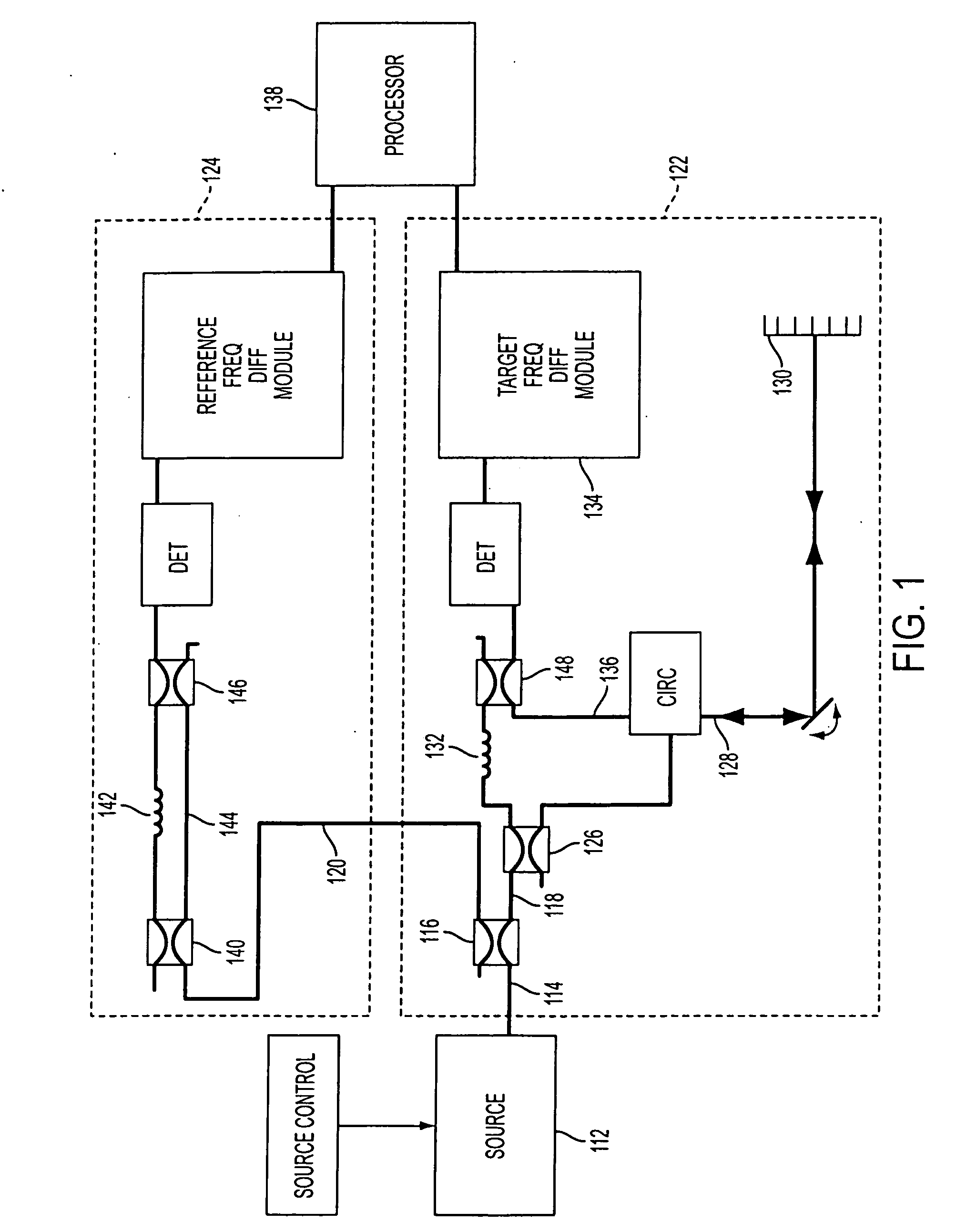
[0034]FIG. 1 illustrates a conventional frequency modulated laser radar system 110. System 110 typically includes a laser source 112 that emits a beam 114 of electromagnetic radiation. Beam 114 may be emitted at a frequency that is continuously varied, or chirped. In some instances, chirping the frequency may include sweeping the frequency between a lower frequency and an upper frequency (or vice versa) in a periodic manner (e.g. a sawtooth waveform, a triangle waveform, etc.). Beam 114 may be divided by an optical coupler 116 into a target beam 118 and a reference beam 120.

[0035] In conventional embodiments, system 110 may include a target interferometer 122 and a reference interferometer 124. Target interferometer 122 may receive target beam 118, and may divide the target beam at an optical coupler 126. Target interferometer 122 is typically used to generate a target signal that may depend upon a range of a target 130 from target interferomete...


PUM


Abstract

A laser radar system using collocated laser beams to unambiguously detects a range of a target and a range rate at which the target is moving relative to the laser radar system. Another aspect of various embodiments of the invention may relate to a laser radar system that uses multiple laser radar sections to obtain multiple simultaneous measurements (or substantially so), whereby both range and range rate can be determined without various temporal effects introduced by systems employing single laser sections taking sequential measurments. In addition, other aspects of various embodiments of the invention may enable faster determination of the range and rate of the target, a more accurate determination of the range and rate of the target, and/or may provide other advantages.

Description

RELATED APPLICATIONS [0001] This application claims priority from U.S. Provisional Patent Application Serial No. 60 / 651,989, filed Feb. 14, 2005, and entitled “Chirped Coherent Laser Radar System and Method.”FIELD OF THE INVENTION [0002] The invention relates generally to a measuring device and more particularly to a chirped coherent laser radar system. BACKGROUND OF THE INVENTION [0003] Various measuring devices for measuring linear distances using one or more laser radars are known. Such measuring devices may generate information related to a distance or range of a target from the measuring device and / or a velocity, or range rate, of the target relative to the measuring device. This range and range rate information may be useful in a variety of settings. For the purposes of this application the term range rate refers to the rate of change in the range between the target and the measuring device. [0004] A typical measuring device may include, for example, a frequency modulated lase...

Claims


Application Information

Patent Timeline
IPC IPC(8): G01C3/08G01S7/4911G01S17/32G01S17/34
CPCG01C3/08G01S7/4818G01S17/32G01S7/4814G01S7/4911G01S17/06G01S17/34
Inventor SEBASTIAN, RICHARDBELSLEY, KENDALL
Owner AEVA INC
Why Eureka
Try Eureka