
Continuous measurement for determining a suitable mounting position or for quality-testing of gear sets

Inactive Publication Date: 2002-09-19
KLINGELNBERG AG
View PDF0 Cites 9 Cited by
  • Summary
  • Abstract
  • Description
  • Claims
  • Application Information

AI Technical Summary

Benefits of technology

[0006] The object is to develop a measuring equation which allows a faster determination of the suitable mounting position of gear sets or a quality test of gear sets.
[0008] It is a further object of the present invention to make available a method, a device, an evaluation unit and a software module, which are suitable for determining a suitable mounting position for the mounting of wheel sets pairs as rapidly as possible.
[0009] It is a further object of the present invention to make available a method, a device, an evaluation unit and a software module, which are suitable for performing a quality test of gear sets as rapidly as possible.
[0011] It is an advantage of the method in accordance with the invention that it permits a test of gear sets without considerable additional time. In contrast to the measuring method described at the outset, wherein measurements are only performed at discrete mounting points, the method in accordance with the invention allows a considerably shorter measuring process. This is of commercial importance, since with a shortened measuring process it is possible to improve the efficiency of the testing system and its throughput.

Problems solved by technology

A disadvantage of this method is that it is relatively time-consuming to approach the individual mounting positions and then to perform a structure-borne sound analysis of single-flank transmission error measurement in every installed position.

Method used


Image

  • Continuous measurement for determining a suitable mounting position or for quality-testing of gear sets
  • Continuous measurement for determining a suitable mounting position or for quality-testing of gear sets
  • Continuous measurement for determining a suitable mounting position or for quality-testing of gear sets

Examples


Embodiment Construction

[0026] For the sake of simplicity, gears and gear sets are mainly mentioned in the present description. In the description, the term wheel set is used as a generic term for every type of gear wheel, spur wheel, bevel wheel (for example the bevel gears), ring gear, pinions, etc. The present invention is particularly suited for the testing of axially displaced and non-axially displaced bevel wheel gears. In this connection it is unimportant whether these are gear wheels with interior teeth or with exterior teeth, or whether the gear wheels are spur- or helically-toothed.

[0027] The suitable positioning of a gear set (for example two gear wheels) is repeatedly mentioned in the present description. It should be noted that the suitable position can depend on various prerequisites. If the gear set is a helical bevel gear intended to be installed in a truck, other criteria are used than with a helical bevel gear for mounting in a small car. Moreover, every user has different prerequisites, ...


PUM


Abstract

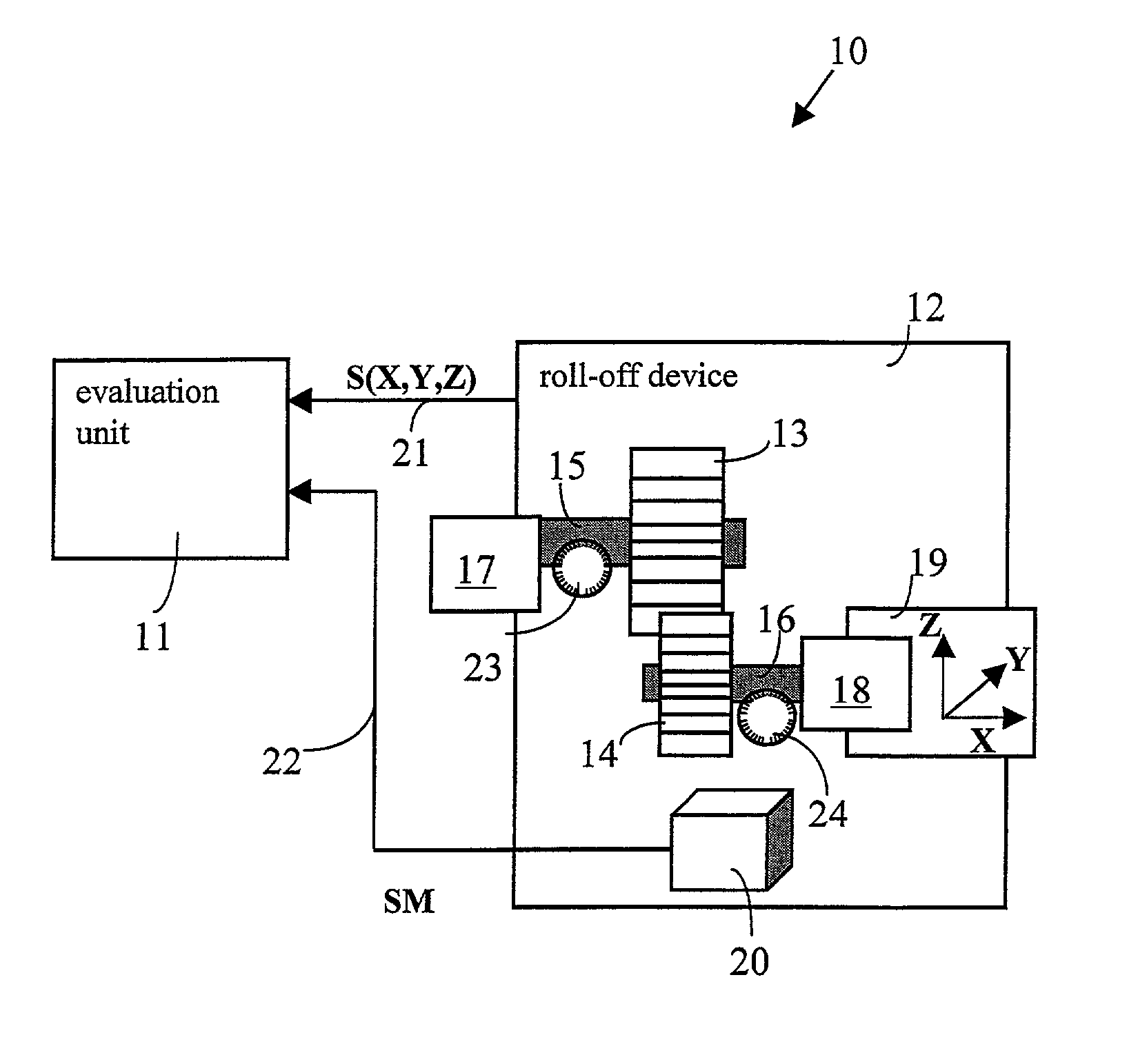
A system for determining the suitable positioning of a first gear wheel in relation to a second gear wheel. The system comprises an evaluation unit and a roll-of device, which contains a first spindle for the rotatable seating of the first gear wheel, a second spindle for the rotatable seating of the second gear wheel and a drive mechanism for rotating the first gear wheel and a drive mechanism for acting with a positive or a negative torque on the second gear wheel. The roll-off device furthermore has a displacement device for changing the positioning of the first gear wheel in relation to the second gear wheel. A measurement pick-up device and two angle encoders are provided in the roll-off device and are connected with the evaluation unit. The evaluation unit processes coordinate information S(X, Y, Z), which describes the positioning of the first gear wheel in relation to the second gear wheel, the continuous signal from the measurement pick-up device, and signals from the two angle encoders, in order to determine the suitable positioning.

Description

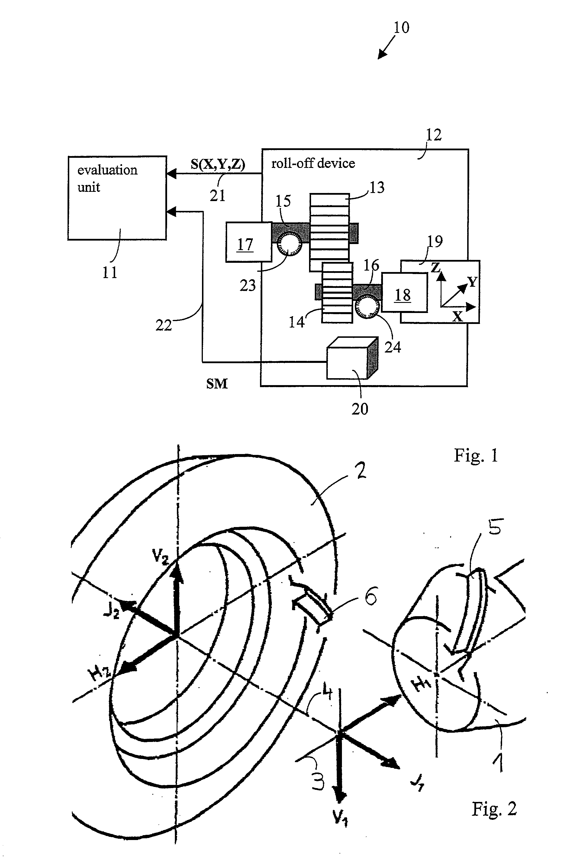
FIELD OF THE INVENTION[0001] The invention relates to a method for determining a suitable mounting position, or for quality-testing of gear sets, as well as an appropriate device, an evaluation unit and a software module for executing the method. The invention is used in particular for determining the suitable mounting position of a gear set, such as is used in transmissions.BACKGROUND OF THE INVENTION[0002] Gear wheels are used in various technical fields. Customarily a first gear wheel meshes with a second gear wheel. To assure the neat roll-off of the gear wheels, it is important to bring the two gear wheels into a relationship with each other in a spatial coordinate system in a suitable manner during the mounting.[0003] A typical example of two meshing gear wheels is a gear in which a ring gear (as the first gear wheel) and a pinion gear (as the second gear wheel) act together as a gear set. In order to assure a neat roll-off behavior of the pinion along the ring gear, a suitabl...

Claims


Application Information

Patent Timeline
IPC IPC(8): G01M13/02G01B21/00
CPCG01M13/021G01M13/028
Inventor BARTELT, VOLKERPAHUD, CHRISTIAN
Owner KLINGELNBERG AG
Learn More