Ultra-tightly coupled global navigation satellite system space borne receiver system

a global navigation satellite and space borne receiver technology, applied in the field of ultra-tightly coupled global navigation satellite system space borne receiver system, can solve the problems of reduced availability, weaker received gnss signals, high relative velocities and doppler effects, etc., and achieves precise position, velocity and time determination, and ultra-tight coupling (utc).

Active Publication Date: 2010-02-23
THE BOEING CO
View PDF7 Cites 9 Cited by
  • Summary
  • Abstract
  • Description
  • Claims
  • Application Information

AI Technical Summary

Benefits of technology

[0011]The present invention provides a new ultra-tight coupling (UTC) Global Navigation Satellite System (GNSS) receiver system for space-borne applications. In an exemplary embodiment of the present invention, precise orbital dynamics models and orbit propagators or Keplerian models replace and / or modify some of the traditional elements of conventional UTC user equipment, such as translational motion sensors and associated inertial navigation system (INS) processing. Using precise orbital dynamics models coupled with modified INS processing and Kalman filter models, embodiments of the present invention provide robust operation and precise position, velocity and time (PVT) determination in the unique environment of space, while enjoying high sensitivity for weak signals, good anti-jam performance, low cost, and high accuracy. Moreover, the use of precise orbital models in accordance with the principles of the present invention enables substantial performance improvement benefit, including the ability to accurately propagate the platform trajectory without GNSS measurements to an accuracy of about one meter per hour compared to a high-grade avionics INS quality of one nautical mile per hour.
[0012]An exemplary embodiment of the present invention achieves the above attributes by modifying the traditional GPS / INS UTC UE architecture by retaining the rotational sensor IMU instruments (e.g. gyro assembly) while replacing the translational motion IMU instruments (e.g. accelerometer assembly) with precise orbit dynamics models implemented in software. The use of orbital dynamics models and rotational sensors allows precise motion prediction for high accuracy for the case of sparse GNSS measurements, precise prediction of the GNSS antenna phase center (APC) motion to enable long coherent integration times to enhance signal-to-noise ratio (SNR) for weak signal processing, enhanced signal processing for other on-board sensors, and long-duration precise orbit propagation in the case of GNSS measurement outages.
[0014]Furthermore, the use of precise orbital models enables a capability that exceeds the terrestrial-based performance of GPS / INS UTC UE for high sensitivity and high anti-jam requirements. Precise orbital dynamics models which are calibrated while GNSS measurements are available (e.g. drag and radiation pressure models) can enable very accurate orbit determination and propagation of the orbital motion for long durations of GNSS measurement outages or when only sparse measurements are available (e.g. for a satellite platform in geosynchronous orbit).

Problems solved by technology

The space environment often creates additional challenges to GNSS UE operation compared to terrestrial UE applications, including: continuous and wide ranges of platform rotational motions, intermittent antenna visibility to individual GNSS satellites, reduced availability of GNSS signals, weaker received GNSS signals, high relative velocities and Doppler effects, larger relativistic effects, larger signal dynamic range, and increased sensitivity to timing errors.
The use in GPS / INS UTC space borne UE of inertial measurement unit (IMU) accelerometer instruments, such as for sensing translational motion, entails substantial costs, including the cost of space qualifying the associated electronics.
Conventional non-UTC GPS UE which implement random motion models for acceleration or jerk can introduce significant error for rotating satellites, especially if no correction is applied to relate the satellite center of gravity (CG) location to the GPS solution as computed for measurements made at the GPS antenna.
The subject matter of U.S. Pat. No. 5,909,381, however, does not attempt to correct the satellite orbit prediction using state error models with GPS receiver measurements of L-band ranging signals broadcast by the GPS satellites.
The use of GPS receivers on GPS satellites is generally not practical because of the jamming of the receiver due to the proximity of the satellite transmitter and GPS radio frequency (RF) signal radiator.

Method used


Image

  • Ultra-tightly coupled global navigation satellite system space borne receiver system
  • Ultra-tightly coupled global navigation satellite system space borne receiver system
  • Ultra-tightly coupled global navigation satellite system space borne receiver system

Examples


Embodiment Construction

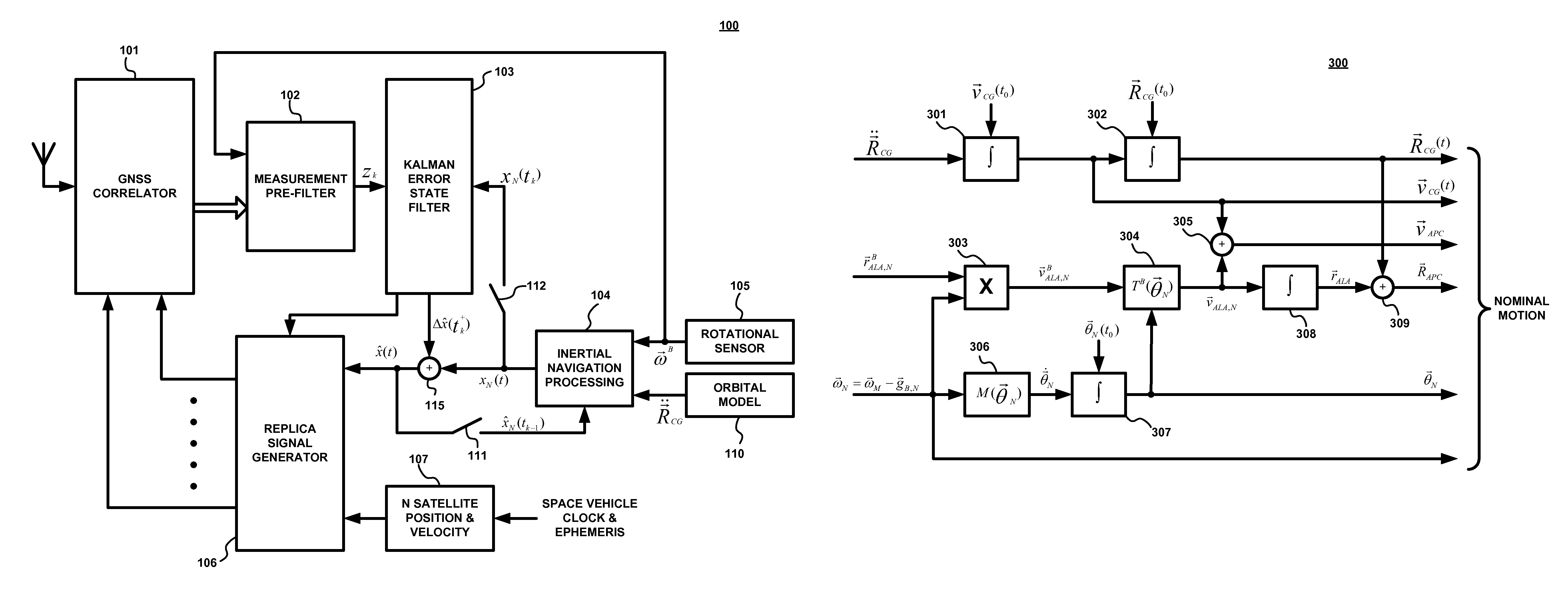
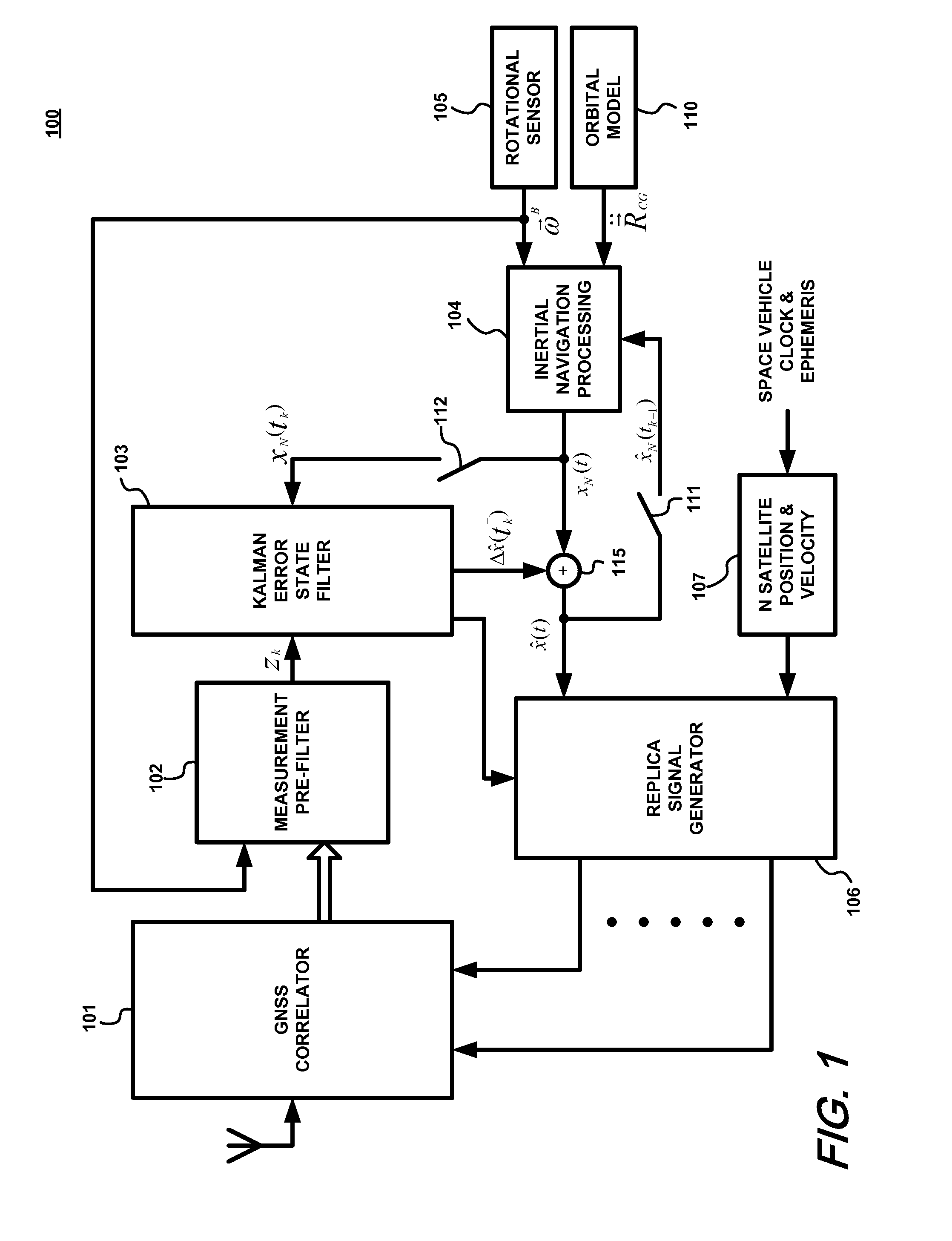
[0020]FIG. 1 shows a block diagram of an exemplary embodiment of a Global Navigation Satellite System (GNSS) receiver 100 in accordance with the present invention for use in a space platform, such as a satellite, for example. The vehicle which carries the receiver 100 will be referred to herein as the platform. The exemplary GNSS receiver 100 comprises a GNSS correlator block 101, a measurement pre-filter block 102, a Kalman error state filter block 103, an inertial navigation processing block 104, a rotational sensor block 105, an orbital model block 110, a replica signal generator block 106, and a satellite position and velocity block 107. The GNSS receiver 100 employs several of the same elements as a conventional GPS / INS UTC UE, such as described in U.S. Pat. No. 6,516,021, including blocks 101-107. U.S. Pat. No. 6,516,021 is hereby incorporated by reference in its entirety into the present Patent Application. As will be described in greater detail below, however, the inertial n...


PUM


Abstract

A GNSS ultra-tight coupling (UTC) receiver architecture applicable to space borne orbit platforms is described. A receiver in accordance with this architecture retains the rotational motion sensors typically found in an inertial measurement unit (IMU) of a conventional UTC receiver, but replaces the IMU accelerometer sensors with precise orbital dynamics models to predict the translational motion of the platform center of gravity (CG). Drag and radiation pressure may be modeled as well. The various models can be implemented in software. The IMU rotational sensors are retained for compensation of the GNSS antenna lever arm effect due to platform rotation.

Description

FIELD OF THE INVENTION[0001]The present invention relates generally to Global Navigation Satellite Systems (GNSS) methods and systems, and particularly to ultra-tightly coupled (UTC) GNSS receiver systems for space platform user applications.BACKGROUND INFORMATION[0002]A Global Navigation Satellite System (GNSS), such as the Global Positioning System (GPS), typically comprises a constellation of navigation satellites in Medium Earth Orbit, a ground Control Segment that controls these satellites, and user equipment (UE). The navigation satellites broadcast precisely synchronized ranging signals. The GNSS UE acquire and lock on to the signals from multiple satellites, make precise ranging measurements to the satellites, apply corrections, and apply navigation filter algorithms to solve for the UE position, velocity and time (PVT).[0003]GNSS UE can also operate in the space environment, such as on board satellites. The space environment often creates additional challenges to GNSS UE op...

Claims


Application Information

Patent Timeline
Patent Type & Authority Patents(United States)
IPC IPC(8): B64G3/00G01C21/00
CPCB64G3/00G01S19/47
Inventor DIESPOSTI, RAYMOND STEKAWY, JONATHAN A
Owner THE BOEING CO
Why Eureka
Try Eureka