
Camera with acceleration sensor

a technology of acceleration sensor and camera, applied in the field of cameras, can solve problems such as reliability problems, and achieve the effect of reducing movement-induced image blurring and adjusting image exposure tim

Inactive Publication Date: 2006-09-14
WEINBERG HARVEY +3
View PDF41 Cites 101 Cited by
  • Summary
  • Abstract
  • Description
  • Claims
  • Application Information

AI Technical Summary

Benefits of technology

[0005] display an artificial horizon indicator on a viewfinder to aid in orienting the camera;
[0007] use camera movement information to determine a minimum shutter speed, to reduce motion-induced picture blurring; and
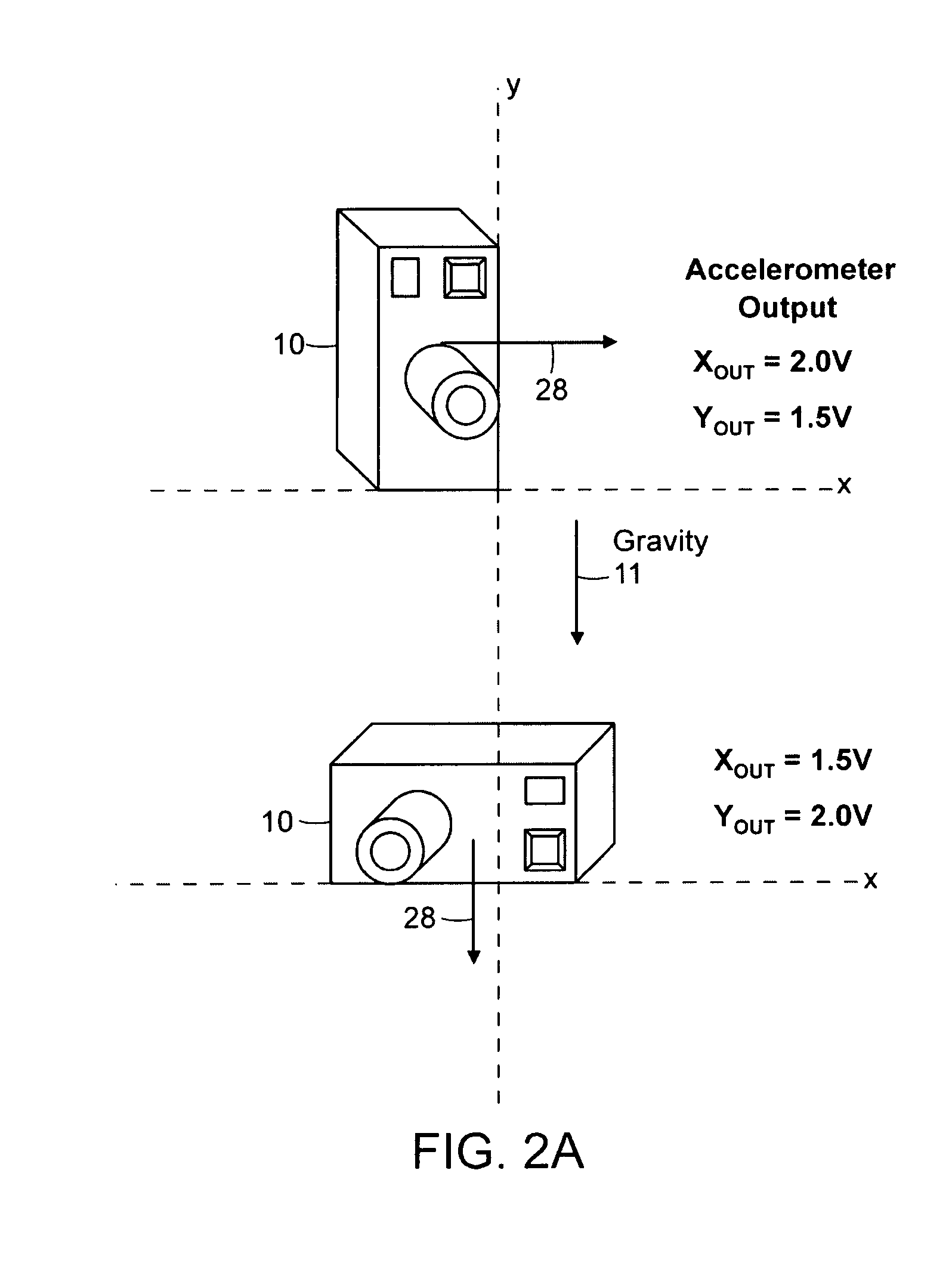
[0009] In one embodiment, the accelerometer provides orientation information for the camera with respect to the earth's gravity. This orientation information allows an artificial horizon indicator to be displayed on an image on a display surface, such as a viewfinder display attached to the camera. The user views the artificial horizon indicator and may realign the camera based on the relationship between the image and the indicator.
[0011] A further embodiment of the invention adjusts image exposure time for a camera to reduce movement-induced image blurring. An accelerometer mounted to the camera provides acceleration information. The information is stored and peak-to-peak acceleration magnitude is calculated for the most recent time period. When picture taking is initiated, a minimum shutter speed is calculated as a function of the peak-to-peak acceleration magnitude over the most recent time period and the focal length of the camera. The exposure time of the picture may be adjusted accordingly.

Problems solved by technology

Ball and cage type mechanical switches can be used to ascertain orientation, but they have reliability problems.

Method used


Image

  • Camera with acceleration sensor
  • Camera with acceleration sensor
  • Camera with acceleration sensor

Examples


Embodiment Construction

[0025] In various embodiments of the invention, an accelerometer can be used to determine the static orientation of a camera by measuring the direction of the earth gravity's (gravity vector) relative to the camera body. Other embodiments of the invention use an accelerometer to detect the dynamic movement of a camera. Orientation and / or dynamic movement information for a camera enable a variety of functions. Several such functions are discussed below in separate sections.

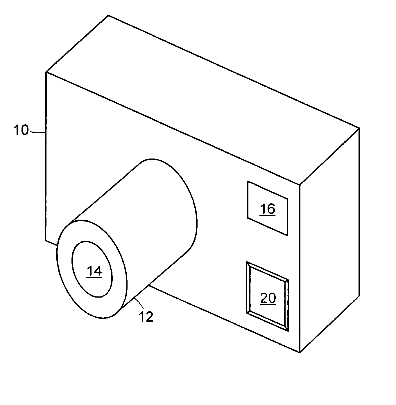
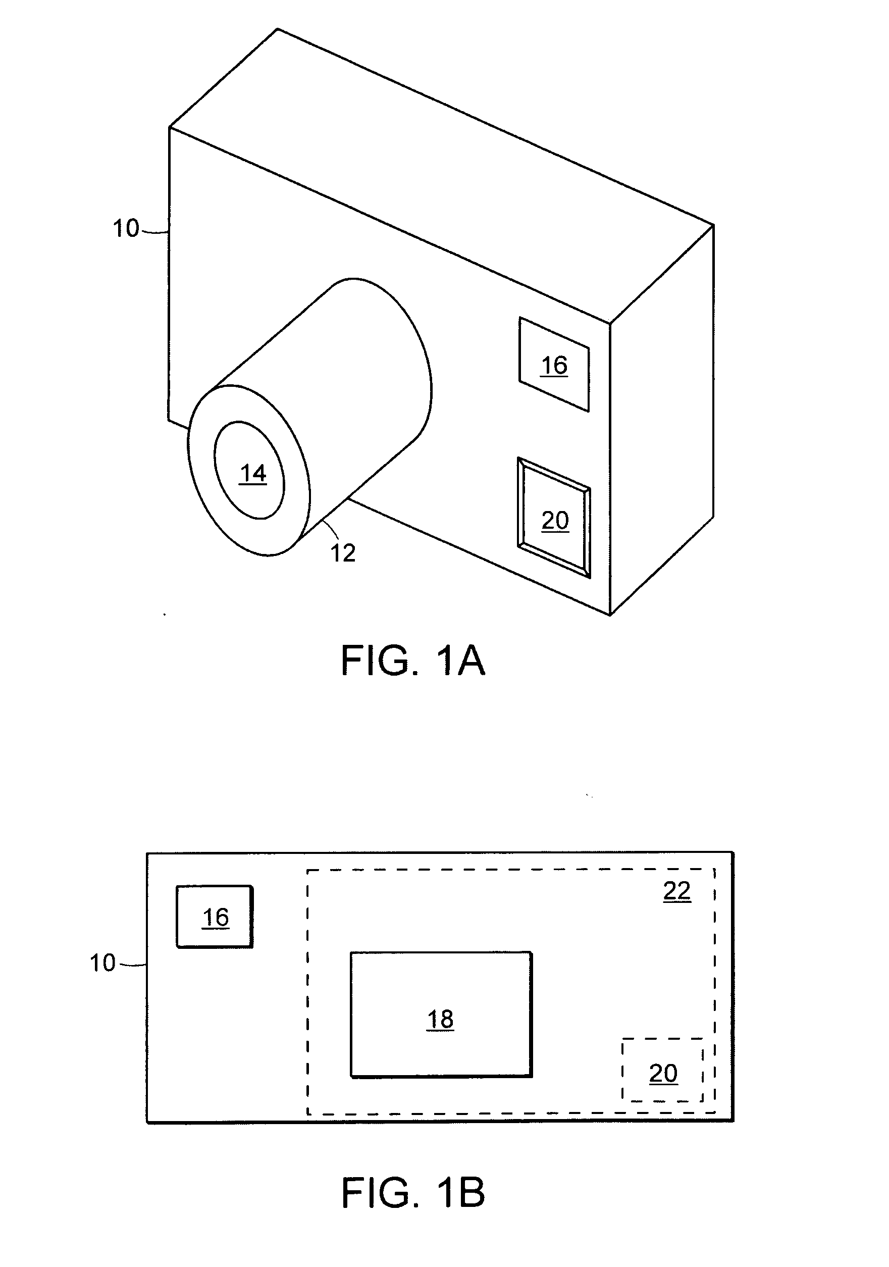
[0026]FIG. 1A is a simplified perspective view of the front of an exemplary camera 10, according to an embodiment of the invention. The camera 10 includes a lens 12 with a lens aperture 14. A viewfinder window 16 allows a user to frame a picture. Pressing a shutter switch 18 initiates picture taking. FIG. 1B shows a plan view of the rear of the camera. The user looks into the viewfinder window 16 and adjusts the camera's orientation to frame the picture. Alternatively, the user may look at a viewfinder display scr...


PUM


Abstract

A method and system for determining camera positioning information from an accelerometer mounted on a camera. The accelerometer measures the orientation of the camera with respect to gravity. Orientation measurement allows user interface information to be displayed in a “right side up” orientation on a viewfinder for any camera orientation. Alternatively, an artificial horizon indicator may be displayed in the viewfinder. The accelerometer may also measure camera movement. Camera movement information together with camera orientation can be used to determine camera usage. Additionally, camera movement information can be used to determine a minimum shutter speed for a sharp picture.

Description

[0001] This application claims priority from U.S. provisional patent application Ser. No. 60 / 648,780, filed Feb. 1, 2005, entitled “CAMERA WITH ACCELERATION SENSOR” and bearing attorney docket number 2550 / A59, the disclosure of which application is incorporated herein by referenceFIELD OF THE INVENTION [0002] The invention generally relates to cameras and, more particularly, the invention relates to detecting motion of a camera. BACKGROUND [0003] In many cases, it is desirable to know the orientation of a camera. A digital camera, for example, could use this information to store the image such that it displays “right side up” on a computer display. Ball and cage type mechanical switches can be used to ascertain orientation, but they have reliability problems. SUMMARY OF THE INVENTION [0004] In accordance with embodiments of the invention, a digital camera includes an accelerometer mounted on the camera. The accelerometer measures camera movement and / or orientation. In various embodi...

Claims


Application Information

Patent Timeline
IPC IPC(8): G03B17/00
CPCG03B7/00G03B17/02G03B17/20H04N5/232H04N5/2327H04N5/23293H04N23/651H04N23/684H04N23/633H04N23/631
Inventor WEINBERG, HARVEYLEMAIRE, CHRISTOPHESAMUELS, HOWARDJUDY, MICHAEL
Owner WEINBERG HARVEY
Learn More