Unlock instant, AI-driven research and patent intelligence for your innovation.
Methods and apparatus for pumping and dispensing
What is Al technical title?
Al technical title is built by PatSnap Al team. It summarizes the technical point description of the patent document.
a technology of liquid and pumping mechanism, applied in the direction of positive displacement liquid engine, pump, liquid transfer device, etc., can solve the problems of poor quality or high cost, many problems with existing dispensers, high failure rate of pumping mechanism, etc., to improve pumping performance, improve accuracy, and easy to remove
Active Publication Date: 2006-09-21
LANCER PARTNERSHIP
View PDF24 Cites 9 Cited by
Summary
Abstract
Description
Claims
Application Information
AI Technical Summary
This helps you quickly interpret patents by identifying the three key elements:
Problems solved by technology
Method used
Benefits of technology
The present invention provides methods and apparatus for pumping and dispensing liquids that overcome the problems of prior art systems. The invention includes a peristaltic pump with a base and motor housing that can easily disengage for cleaning and maintenance. The pump includes a performance identifier that identifies any deviation in pumping performance and the motor controls the pump based on the identifier. The invention also includes a self-sealing dispensing valve that is bonded to the tube and a tamper-evident seal may be provided. The invention also provides a cold source and water lines for dispensing water at the dispensing point. The technical effects of the invention include improved accuracy, easy cleaning and maintenance, and improved pump performance.
Problems solved by technology
Unfortunately, many problems exist with existing dispensers.
For example, in some dispensers, the accuracy of the pumping is low, resulting in poor quality or high costs, or both.
Also, in some dispensers, there are high failure rates in the pumping mechanism.
Also, the cost of the dispensers or the packaging for the liquid to be dispensed is often too high.
Another area of concern is cleanliness; many dispensers are hard to clean.
Still other issues arise with the difficulty with which the liquid packaging is loaded into and removed from the dispenser, and the dripping that can occur with such loading and removal.
Indeed, attempts to prevent dripping often add unwarranted cost, and can cause system failures where they require a user to remember to move a valve from a closed to an open position after loading of a new package.
Method used
Image
Click on the blue label to locate the original text in one second.
Reading with bidirectional positioning of images and text.
Examples
Embodiment Construction
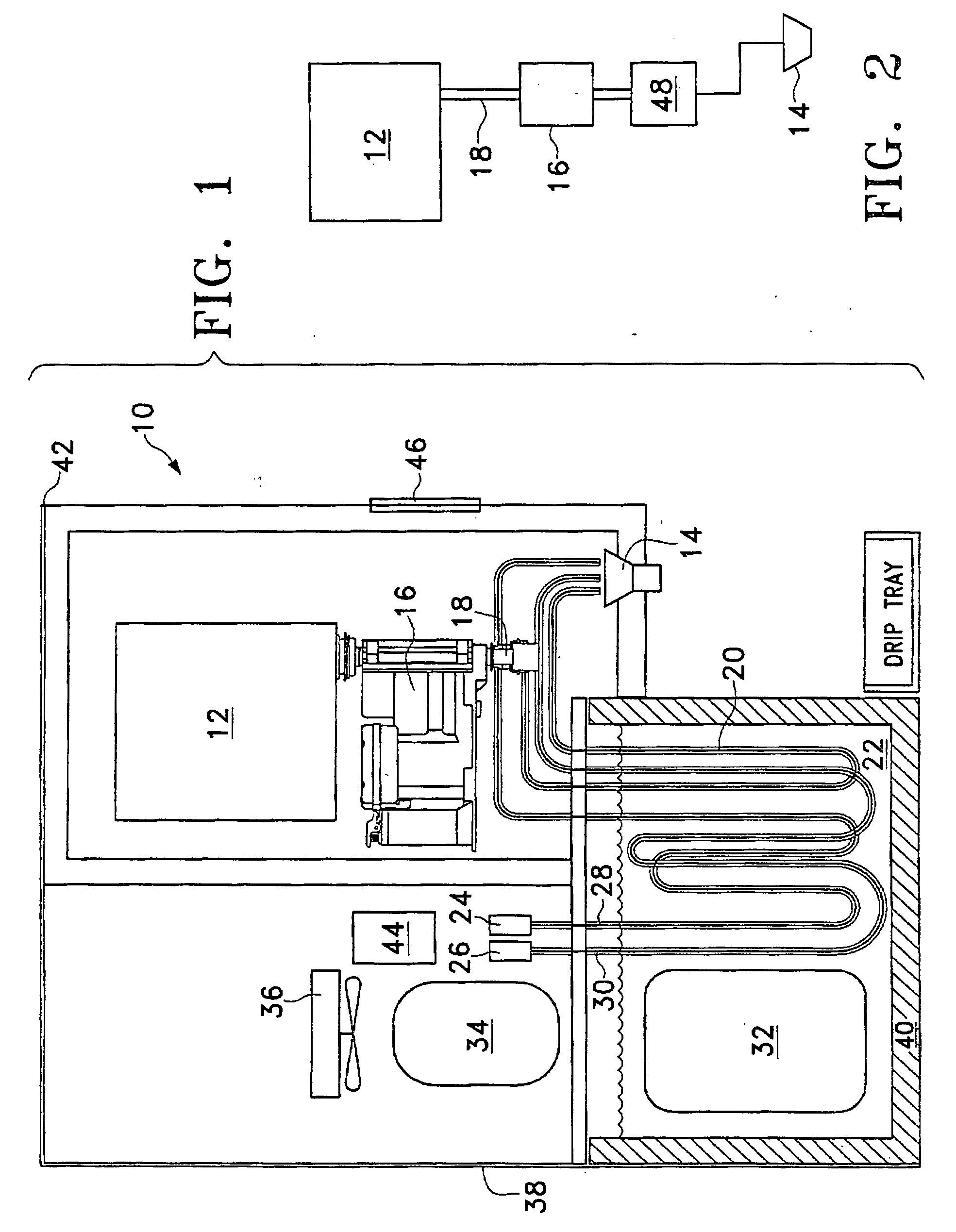
[0025]FIG. 1 illustrates a dispenser 10 used to dispense a liquid from a package 12. In the particular example illustrated, the liquid is a drink concentrate, such as a soft drink syrup, a juice concentrate, or a milk concentrate, and is to be mixed with plain or carbonated water to form a finished drink. The liquid is dispensed through a dispensing point, which may be a nozzle 14, into any suitable receptacle, such as a cup (not shown). A peristaltic pump 16 pumps the liquid from the package 12 toward nozzle 14. The liquid is pumped through a tube 18, which is coupled to the package 12 directly or through a fitment or any suitable coupling approach. Tube 18 may also be coupled directly to the nozzle 14, or it may be coupled to the nozzle 14 through intermediate steps. For example, as shown in FIG. 1, the tube 18 may be coupled to a line 20, which runs through an ice / water bath 22 for cooling the liquid. Line 20 may take a circuitous path through the ice / water bath 20, such as, with...
PUM
Abstract
Methods and apparatus for pumping and dispensing are provided in which a peristaltic pump (16, 64) pumps liquid from a package (12), and may be integrated in a dispenser (10). The peristaltic pump (64) is adapted for improved accuracy, cleaning, and maintenance. Also provided are improved tubes (18) for peristaltic pumping that are coupled to self-sealing dispensing valves (92, 104, 110, 120).
Description
TECHNICAL FIELD OF THE INVENTION [0001] This invention relates generally to the movement of liquids, and more particularly to methods and apparatus for pumping and dispensing liquids or semi-liquids such as, without limitation, concentrates, syrups, beverages, milks, cheeses, condiments, soups, sauces, pharmaceuticals, and other edible or drinkable products. BACKGROUND OF THE INVENTION [0002] Many dispensers exist for dispensing liquids. Some dispensers mix one liquid, such as a juice or syrup, with another, such as water, to form a finished product. Others, such as some cheese dispensers or pharmaceutical dispensers, need not perform such mixing. Whatever the application, it is important that the dispensers perform reliably, that they dispense the correct amount of liquids, and that they are cost effective (among other considerations). [0003] Unfortunately, many problems exist with existing dispensers. For example, in some dispensers, the accuracy of the pumping is low, resulting i...
Claims
Application Information
Patent Timeline
Application Date:The date an application was filed.
Publication Date:The date a patent or application was officially published.
First Publication Date:The earliest publication date of a patent with the same application number.
Issue Date:Publication date of the patent grant document.
PCT Entry Date:The Entry date of PCT National Phase.
Estimated Expiry Date:The statutory expiry date of a patent right according to the Patent Law, and it is the longest term of protection that the patent right can achieve without the termination of the patent right due to other reasons(Term extension factor has been taken into account ).
Invalid Date:Actual expiry date is based on effective date or publication date of legal transaction data of invalid patent.
Patent Type & Authority Applications(United States)