Methods and Apparatus for Implants and Reconstruction

a technology for implants and reconstruction, applied in the field of bone implants, can solve the problems of eccentric implants, hygienic and aesthetic problems, and the need for more complex osteotomies in preparation, and achieve the effects of reducing the risk of infection, and improving the quality of li

Inactive Publication Date: 2016-07-28
SIMMONS JR EARL WAYNE
View PDF24 Cites 3 Cited by
  • Summary
  • Abstract
  • Description
  • Claims
  • Application Information

AI Technical Summary

Benefits of technology

[0008]In accordance with the teachings of the present invention, methods and apparatus for implants and reconstruction are provided which eliminate or substantially reduce the problems associated with prior art systems. Moreover, although the present invention will be discussed in terms of a dental application, it has application in orthopedics in general.
[0014]Important technical advantages are provided by the present invention. In particular, a stable, secure implant is provided by using a coupler to couple a base to an anchor that is already set in bone. Also, eccentric osteotomy sites may be more effectively developed with the present invention, because the anchor provides a stable platform for working a cutting instrument to create the desired osteotomy shape.

Problems solved by technology

However, well known functional, hygienic, and aesthetic problems can be associated with concentric implants.
However, eccentric implants present their own difficulties.
For example, they generally require more complex osteotomies in preparation for the implants.
And, if an implant site is not properly prepared, the implant may not integrate with the jawbone with sufficient strength to provide adequate stability.
As examples of poor implant sites, sites may be too large, or too deep, or too shallow, or too tapered, or mismatched to the shape of the implant, leading to voids or insufficient jawbone-to-implant surface contact, or to hygienic or aesthetic problems.
Relatedly, if the implant site is too deep, resorbed, vertically depressed from bone loss, or too tapered, there may be insufficient bone mass available for adequately securing an implant anchor.
The junctions between the components themselves and to bone must not result in voids or allow movement, which can lead to implant failure.
Similar problems and needs exist in general orthopedics as well.

Method used


Image

  • Methods and Apparatus for Implants and Reconstruction
  • Methods and Apparatus for Implants and Reconstruction
  • Methods and Apparatus for Implants and Reconstruction

Examples


Embodiment Construction

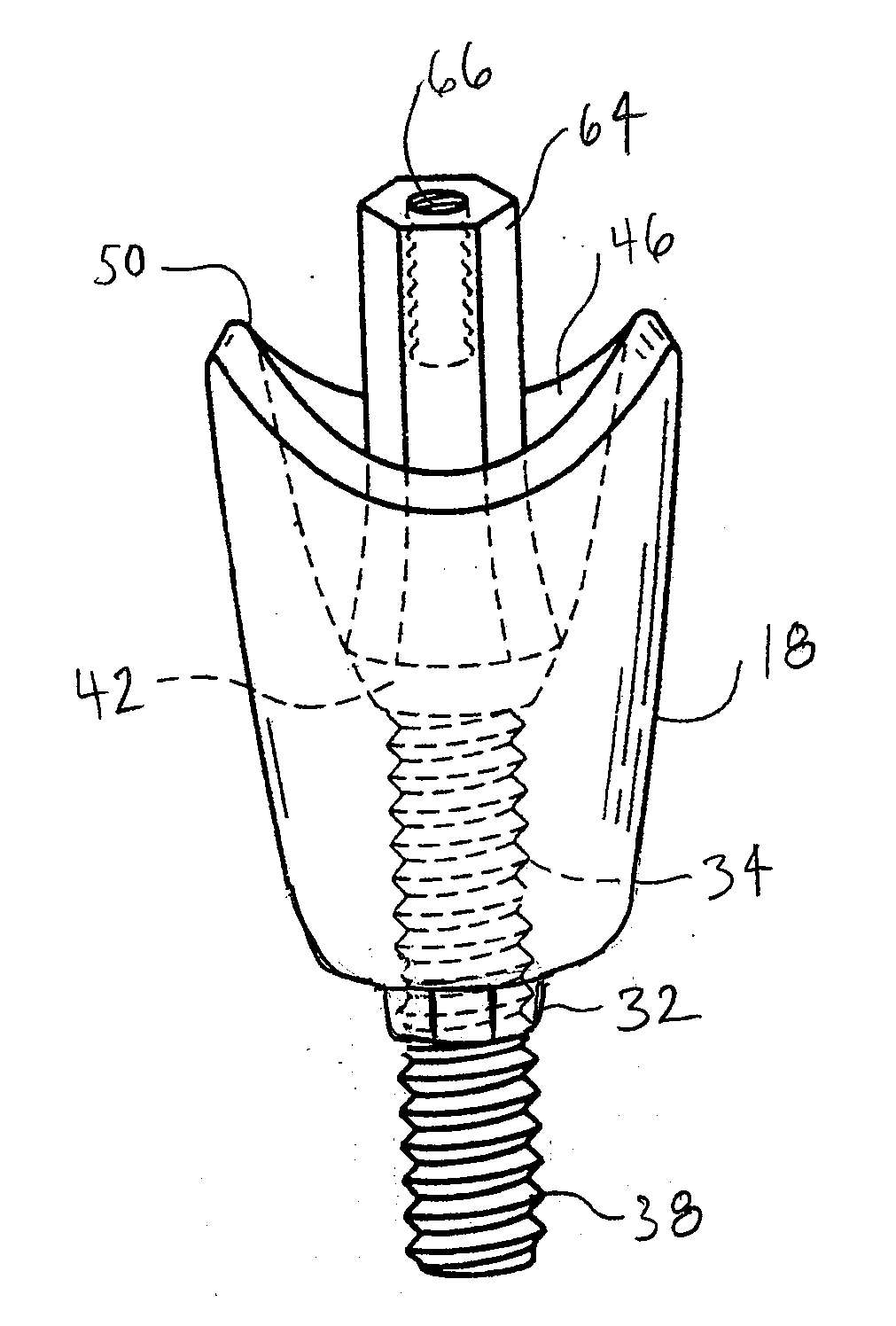
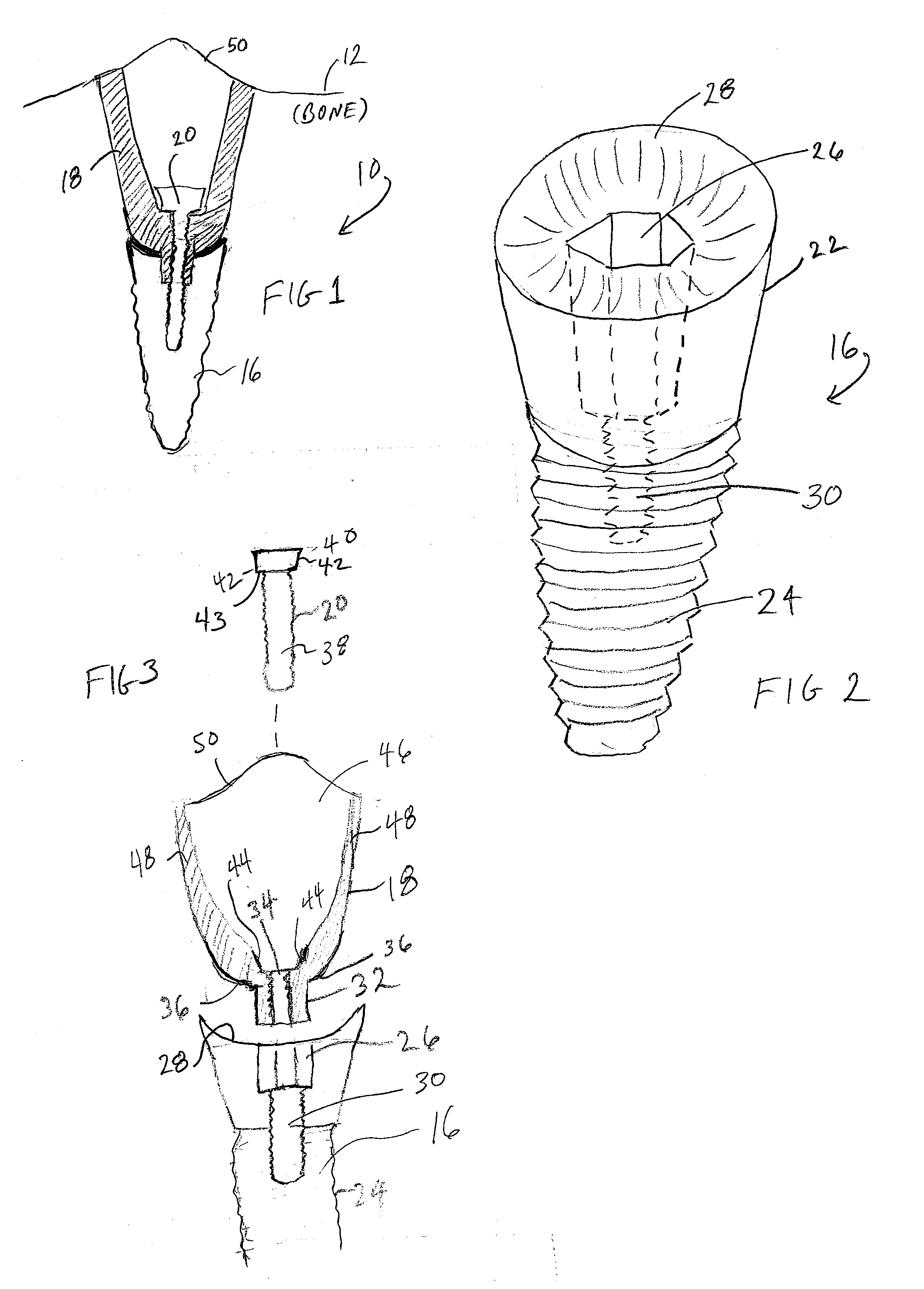
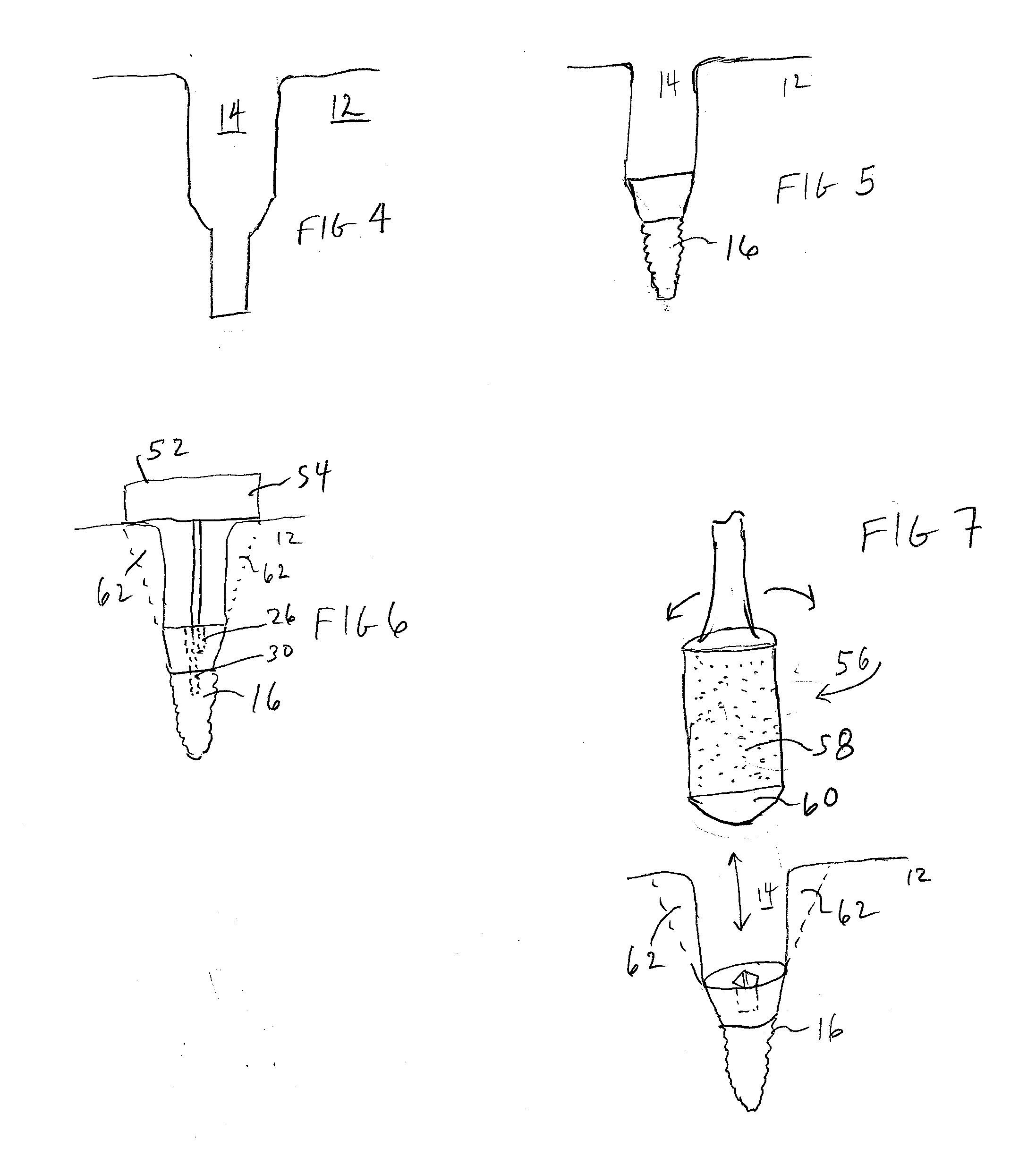
[0021]FIG. 1 illustrates one embodiment of a dental implant 10 according to the teachings of the present invention. Implant 10 is implanted into bone 12 at site 14. Preparation of site 14 will be described below. Implant 10 includes anchor 16, base 18, and coupler 20. Anchor 16 is set into the bone, and then base 18 is coupled to the anchor 16 with coupler 20. Anchor 16, base 18, and coupler 20 may be made of any suitable material, including, without limitation surgical grade metals. The components in contact with bone, such as anchor 16 and base 18, are preferably made of surgical grade Titanium or Zirconium, although any suitable material, such as, without limitation, sapphire, may be used.

[0022]FIG. 2 illustrates a particular embodiment of anchor 16. As shown, anchor 16 includes a head 22 threaded section 24. The threaded section 24 allows for osseointegration by screwing. However, any other suitable features, such as, without limitation, barbs, ribs, waists, or inverted ribs, ma...


PUM


Abstract

An implant apparatus and method of reconstruction are provided in which an anchor (16) implanted into bone, and an eccentric base (18) is coupled to the anchor (16) with a coupler (20). A fixture, such as a dental fixture, may be coupled to the base (18).

Description

CROSS-REFERENCE TO RELATED APPLICATION AND PRIORITY INFORMATION[0001]This application claims the benefit of co-pending, prior filed U.S. provisional application no. 62 / 106,655 entitled “Methods and Apparatus for Implants and Reconstruction”, filed Jan. 22, 2015.TECHNICAL FIELD OF THE INVENTION[0002]This invention relates generally to bone implants, and in particular to methods and apparatus for implants and reconstruction.BACKGROUND OF THE INVENTION[0003]In recent years, the use of dental implants has become widespread. Concentrically shaped implants are the most common, and offer relatively easy installation. Their round shape allows the use of conventional drills and screwing techniques. However, well known functional, hygienic, and aesthetic problems can be associated with concentric implants.[0004]Eccentrically shaped implants, which more closely match natural teeth shapes in cross section, may reduce such problems. However, eccentric implants present their own difficulties.[000...

Claims


Application Information

Patent Timeline
Patent Type & Authority Applications(United States)
IPC IPC(8): A61C8/00A61C1/08
CPCA61C8/0077A61C8/0068A61C1/084A61C8/006A61C8/0089A61C8/0069A61C8/0037
Inventor SIMMONS, JR., EARL WAYNE
Owner SIMMONS JR EARL WAYNE
Why Eureka
Try Eureka