
Partial hand prosthesis

a hand and prosthesis technology, applied in the field of hand prosthesis, can solve the problems of providing no active functionality, overuse syndrome of the working limb, and the prosthesis of this type is functional but not cosmetically pleasing

Inactive Publication Date: 2006-09-21
ADVANCED ARM DYNAMICS OF TEXAS
View PDF20 Cites 65 Cited by
  • Summary
  • Abstract
  • Description
  • Claims
  • Application Information

AI Technical Summary

Problems solved by technology

Cosmetic type prosthetic devices are generally passive and provide no active functionality.
This is not generally desired as it unnatural and can lead to complications associated with overuse syndrome of the working limb.
Prosthetic devices of this type are functional but not cosmetically pleasing as they generally don't attempt to mimic the look and feel of a real human hand.
However, with such prior art electro-mechanical prosthetic devices, the normal physiologically unconscious use of the device is difficult as the patient may need to concentrate the action of the muscles or tendons providing the operating force.
Partial hand amputations where the thumb remains intact present a common type of limb deficiency.
Prior art prosthetic devices adapted to such cases pose significant disadvantages due to overall lack of adjustability during use.
Even when the prosthetic device is designed with an opposition post, i.e. a member that resists the motion of one or more working digits of the hand, the lack of feedback to the patient requires the patient to reposition the device for each new task.
No prior art prosthetic is known to effectively utilize the residual thumb and neighboring structures of the remnant portion of the hand in order to help the patient adjust the grip of the device without use of a functional limb.

Method used


Image

  • Partial hand prosthesis
  • Partial hand prosthesis
  • Partial hand prosthesis

Examples


Embodiment Construction

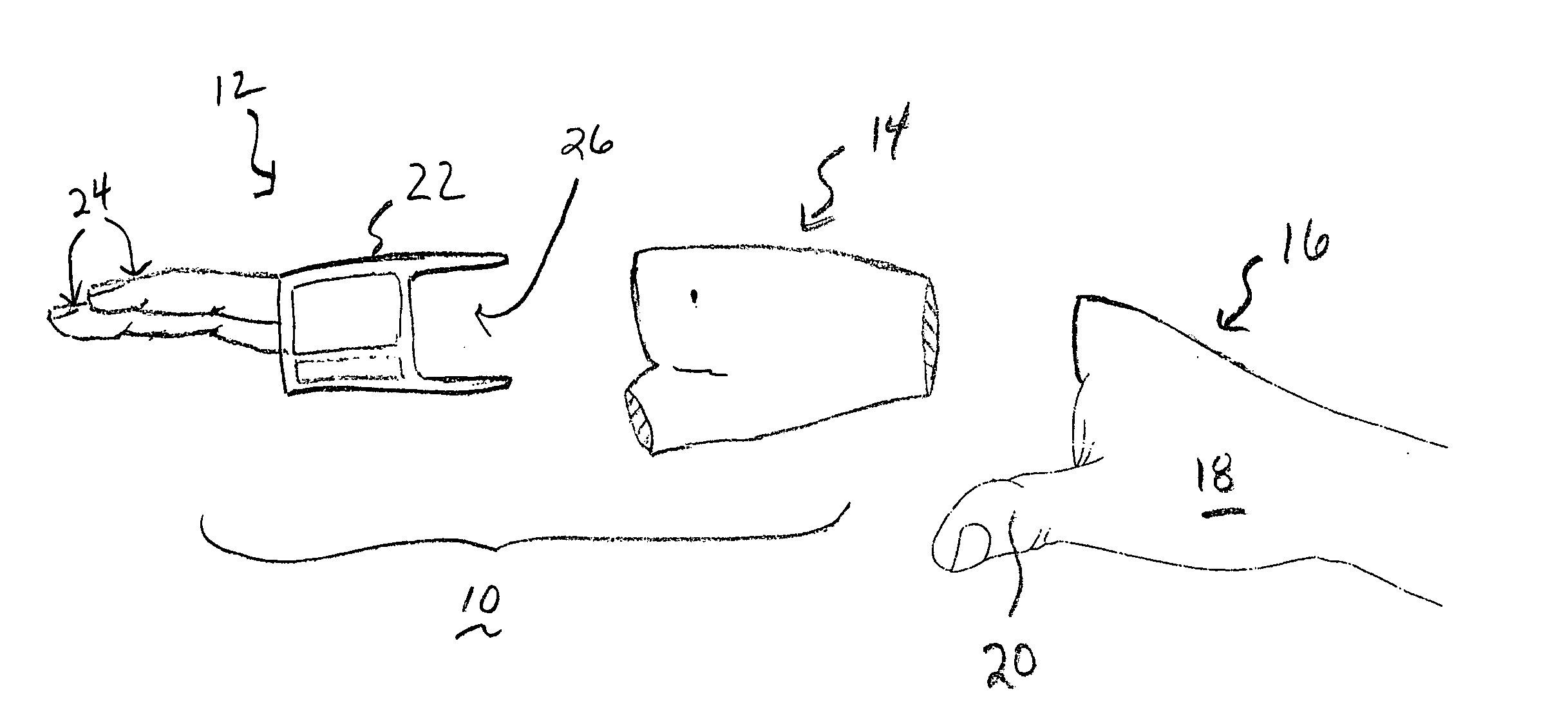
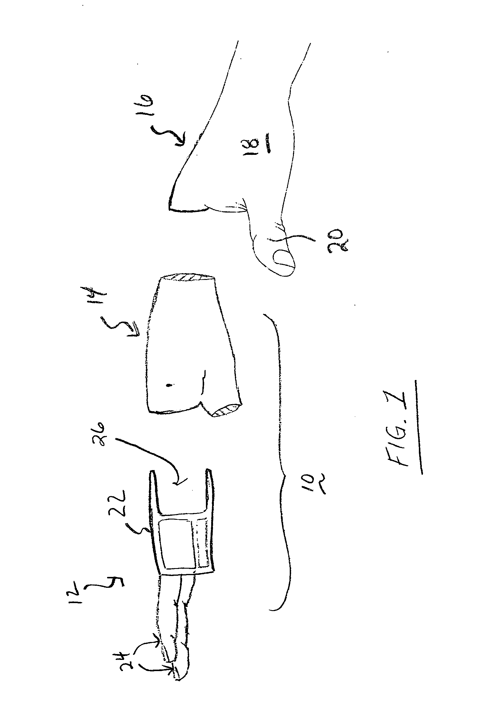
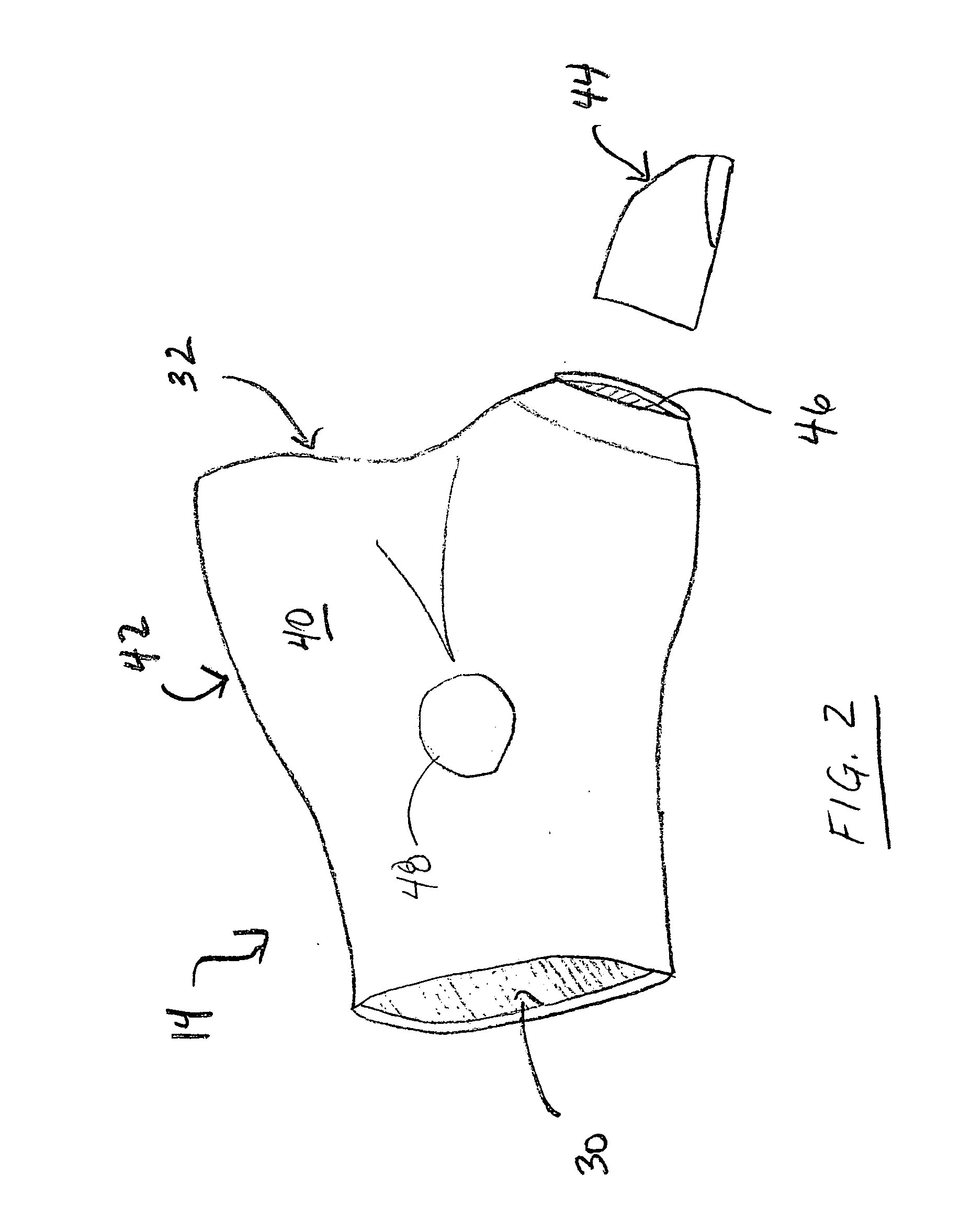
[0016] Referring now to the figures, FIG. 1 shows a prosthetic system, denoted generally as 10, consisting of prosthetic device 12 and liner 14 which are designed to fit over a remnant portion 16 of a hand 18. As shown, hand 18 maintains a working thumb thus remnant portion 16 forms a partial hand and prosthetic system 10 is intended to provide a partial hand prosthesis as described herein. In this regard, prosthetic device 12 includes a harness 22 to which one or more prosthetic fingers 24 are movably attached. In a more general sense, prosthetic fingers 24 are designed to move in a direction towards thumb 20 when prosthetic system 10 is worn by a user to a point where it opposes the movement of thumb 20. As such, the terms “prosthetic fingers”, “finger” or “opposition members” can and will be used interchangeably throughout.

[0017] Liner 14 provides a means for attaching prosthetic device 12 to remnant portion 16 of hand 18. Preferably, liner 14 provides a snug slip-free fit over ...


PUM


Abstract

A prosthetic device (12) and liner (14) form a prosthetic system (10) that can substantially mimic the cosmetic and functional qualities of a human hand. A harness (22) is adapted to fit about a remnant portion (16) of a hand (18). The harness has an opening (26) for accommodating the liner (14). A moveably mounted opposition member (24) is supported by the harness (22) and sensors (60, 62) positioned about the harness (22) detect a force exerted by an area (40) in proximity to the hypothenar eminence of remnant portion. Once a force is detected by either sensor (60, 62) a signal is communicated to a controller (70) which activates a motor (100) causing motion of the opposition member (24).

Description

TECHNICAL FIELD [0001] The present invention relates generally to a prosthetic device for a hand. More specifically, the invention relates to a partial hand prosthesis that substantially replicates the functionality and look of fingers of a human hand. Still more particularly, the invention provides an electro-mechanical fitted and partial hand prosthetic device that senses motion on an area substantially proximate the hypothenar eminence of the remnant portion of a hand in order to activate the motion of a prosthetic finger member moveably attached to a prosthetic harness surrounding the hand. BACKGROUND OF THE INVENTION [0002] Prior attempts have been made to provide a prosthetic device that simulates the look and functionality of the human hand. Most such attempts fall into two camps: cosmetic type prosthesis and active type prosthesis. Cosmetic type prosthetic devices are generally passive and provide no active functionality. Thus, with a cosmetic limb the patient often resorts ...

Claims


Application Information

Patent Timeline
IPC IPC(8): A61F2/54A61F2/70
CPCA61F2/586A61F2/68A61F2/7812A61F2002/30527A61F2002/701A61F2002/704A61F2002/764A61F2220/0025A61F2002/30523A61F2/70
Inventor LAKE, JOSEPH CHRISTOPHERERGO, MICHAEL ALAN
Owner ADVANCED ARM DYNAMICS OF TEXAS
Learn More