
Pivoting storage bin and method of making

a storage bin and movable technology, applied in the field of storage bins, can solve the problems of expensive rework and/or replacement, difficulty in opening or reaching the operating handles of these known overhead storage bins, and problems such as the problem of inserting or removing luggage,

Active Publication Date: 2006-09-28
THE BOEING CO
View PDF11 Cites 54 Cited by
  • Summary
  • Abstract
  • Description
  • Claims
  • Application Information

AI Technical Summary

Benefits of technology

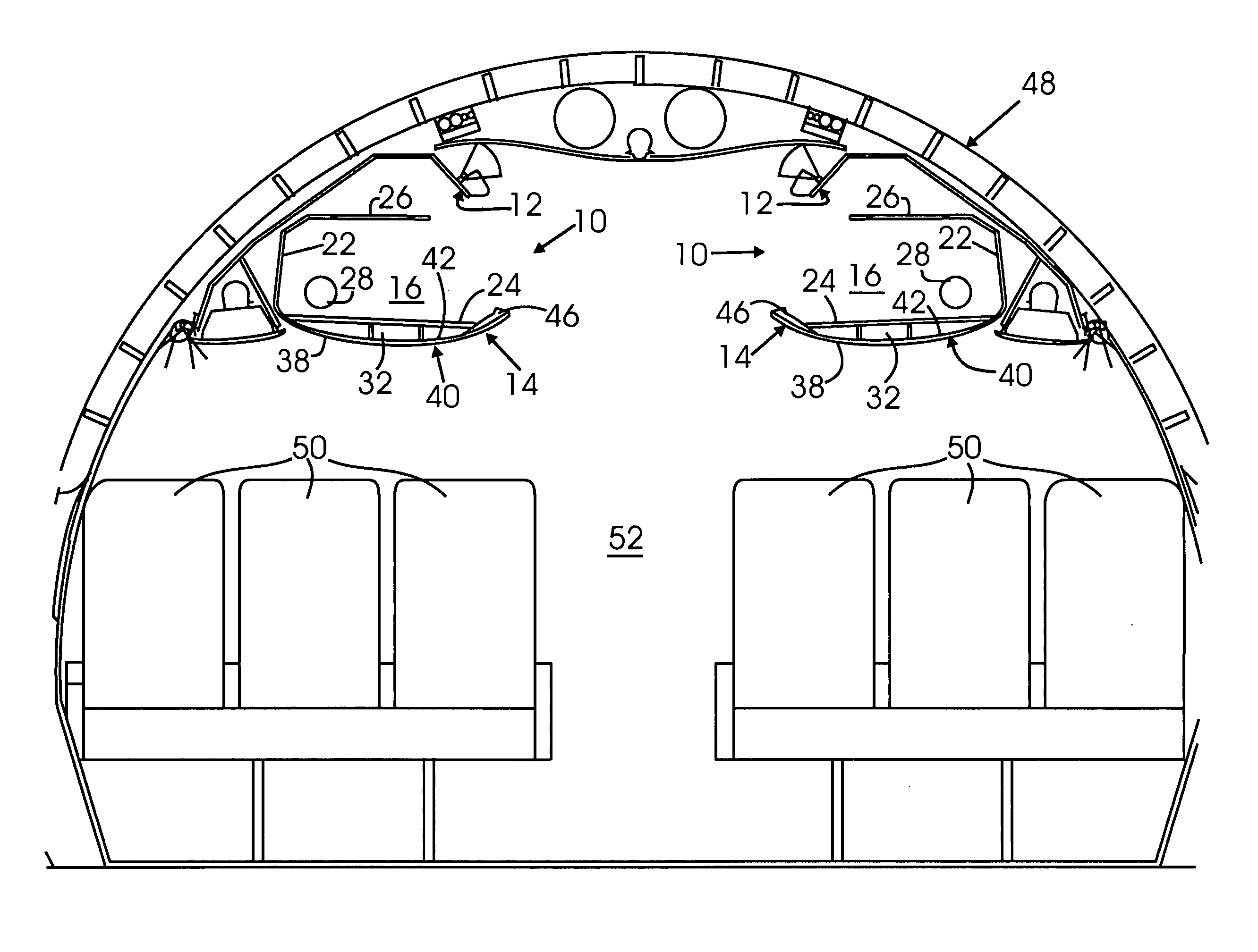
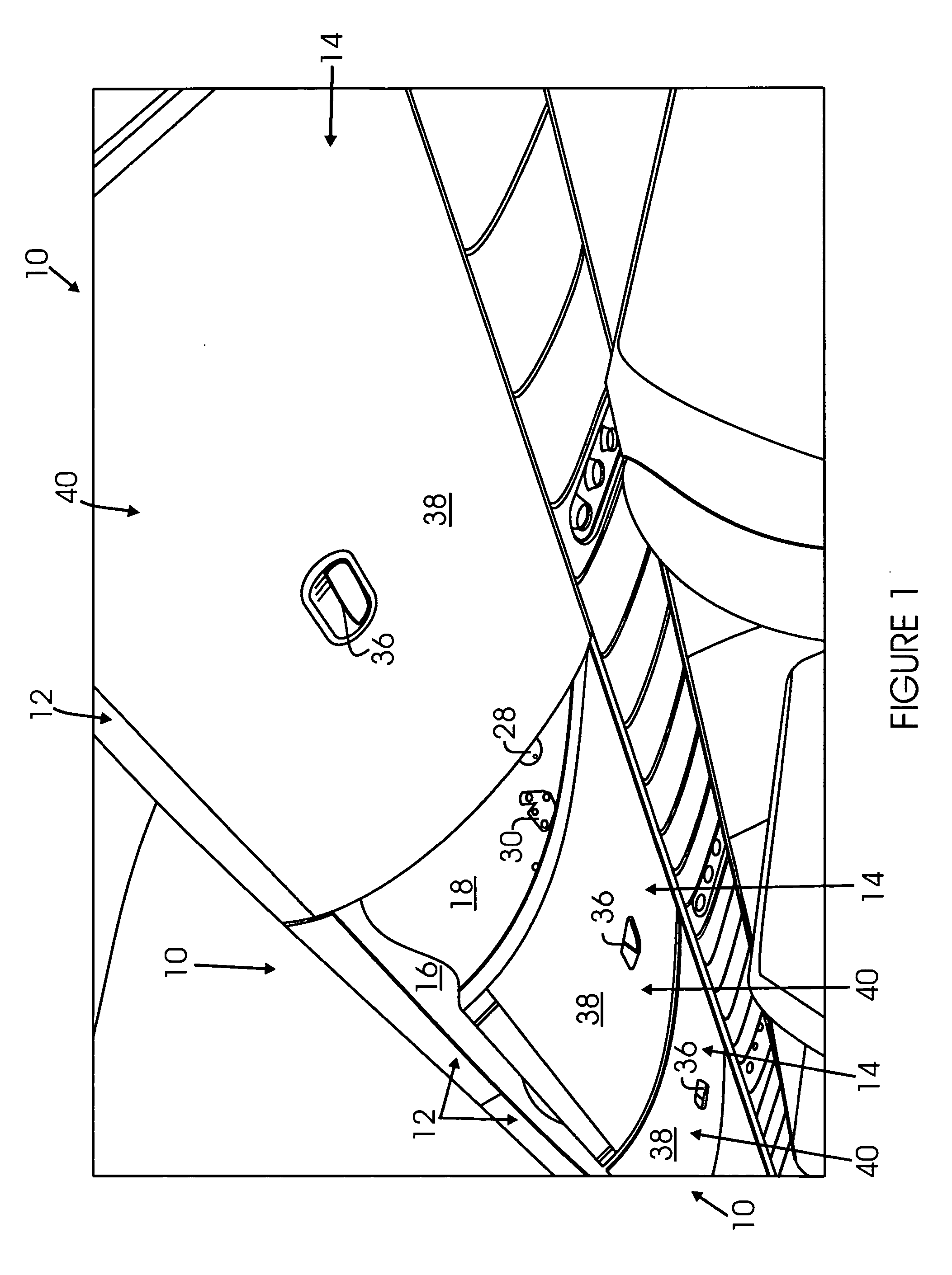
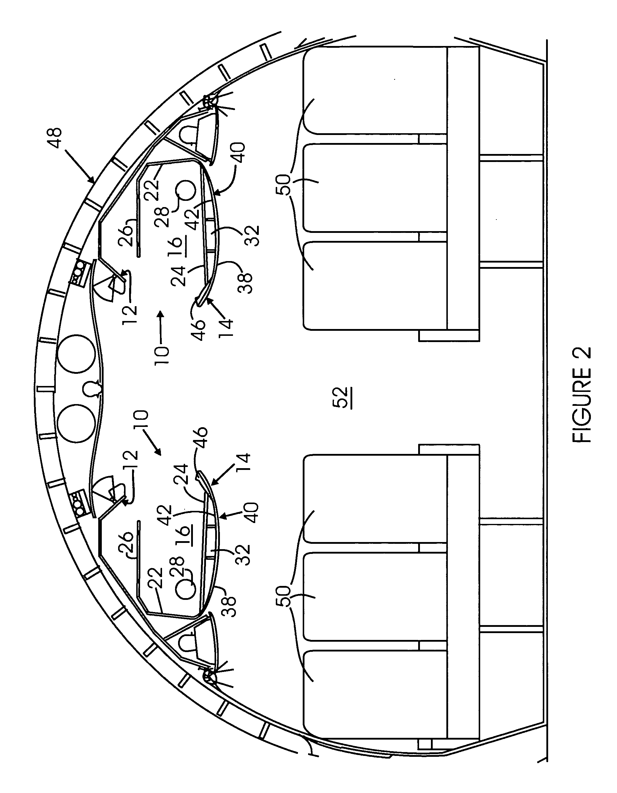
[0009] Accordingly, it is a general object of the present invention to provide an improved storage bin. It is a particular object of the present invention to provide an improved overhead luggage storage bin in a vehicle. It is a further particular object of the present invention to provide an improved overhead luggage storage bin in an aircraft having an upper shroud and a lower bucket with a centrally disposed handle. It is yet another particular object of the present invention to provide an improved overhead luggage storage bin in an aircraft having an upper shroud and a pivoting lower bucket with a centrally disposed operating handle secured in a curved front face operatively connected to an interior latch operating mechanism having a flat bottom panel cove

Problems solved by technology

The operating handles of these known overhead storage bins may be difficult to open or reach by some passengers because of the placement of the operating handle near the top-most portion.
Furthermore, during the assembly or manufacture of the known buckets, small dimples may appear through a covering laminate on the visible front surface of the bucket when an insert is potted on the opposite side of the front of the bucket, thus resulting in the bucket being rejected, causing costly rework and / or replacement.
Additionally, because of the curved interior surface of the front face of the known buckets, and, in particular, latch covers held on the internal surface of the front, problems have occurred in inserting or removing luggage because of the need to “drag” the luggage over the “bump” caused by the latch cover.

Method used


Image

  • Pivoting storage bin and method of making
  • Pivoting storage bin and method of making
  • Pivoting storage bin and method of making

Examples


Embodiment Construction

[0018] The following description is provided to enable any person skilled in the art to make and use the invention and sets forth the best modes contemplated by the inventors of carrying out their invention. Various modifications, however, will remain readily apparent to those skilled in the art, since the generic principles of the present invention have been defined herein specifically to provide for an improved storage bin assembly for a vehicle. The storage bins of the present invention are hereinafter described as overhead pull-down luggage storage bins or pivot stow bins for reasons of explanation only and not by way of limitation. The pivot stow bins include pivoting lower bucket portions having centrally mounted operating handles that are easier to reach and operate. The handles are operatively connected to a latch operating mechanism mounted on the internal surface or wall of the front of the bucket and covered by an internally mounted flat bottom plate. The flat bottom plat...


PUM


Abstract

A storage bin system for holding luggage or the like has an upper shroud portion secured to a supporting structure and a cooperating lower bucket defining a storage space for items. The lower bucket pivots downwardly to open and has a curved front face with curved inner and outer surfaces. A latch handle is centrally mounted in the front surface and operatively connected to a latch operating mechanism secured to the inner surface. A flat bottom plate is removably mounted on the curved inners surface, covering the latch operating mechanism to from a flat surface to support items inserted into the storage space. A number of the storage bin systems are mounted on opposite sides of a passenger cabin of a single aisle aircraft to provide a cleaner, open passenger cabin look.

Description

BACKGROUND OF THE INVENTION [0001] 1. Field of the Invention [0002] This invention generally relates to storage bins, and more particularly, to pivotable stow bins for a vehicle, such as an aircraft, and a method of making such stow bins. [0003] 2. Description of the Prior Art [0004] As more people travel, demand for onboard storage of carry-on luggage has increased, in aircraft, as well as busses, ships, trains and other means of mass transit. The known luggage storage bins take various forms, depending on the size of the vehicle, such as overhead luggage bins in the interior of an aircraft having upwardly swinging doors, or pull-down storage bins. [0005] One type of known overhead stowage bin for an aircraft consists of an upper bin portion (“shroud”) adapted to be mounted to supports and a cooperating lower bin portion (“bucket”) that opens downward for receiving luggage. The bucket includes means to control motion of the bucket, as well as an operating handle on its exterior sur...

Claims


Application Information

Patent Timeline
IPC IPC(8): B64D11/00
CPCB64D11/003
Inventor NOVAK, KEITH H.VALDEZ, ROBERTO T.WALTON, BRENT C.
Owner THE BOEING CO
Learn More