
Magnetic refrigerator

Active Publication Date: 2006-10-05
KK TOSHIBA
View PDF12 Cites 78 Cited by
  • Summary
  • Abstract
  • Description
  • Claims
  • Application Information

AI Technical Summary

Benefits of technology

[0019]FIG. 6 is a plane view showing a rotary refrigerant control valve of

Problems solved by technology

However, the refrigeration technique based on the vapor compression cycle has a serious problem of environmental disruption caused by emission of chlorofluorocarbons.
Chlorofluorocarbon alternatives seem to have a bad influence on the environment.
However, this magnetic refrigeration system has drawbacks of a complex structure incorporating the rotating member in a refrigerant circulation mechanism and insufficient cooling capacity.

Method used


Image

  • Magnetic refrigerator
  • Magnetic refrigerator
  • Magnetic refrigerator

Examples


Embodiment Construction

[0020] A magnetic refrigerator according to an embodiment of the invention will be explained hereinafter with reference to the accompanying drawings.

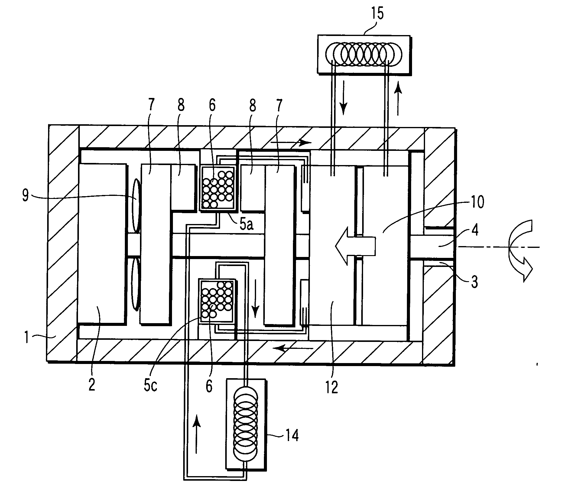
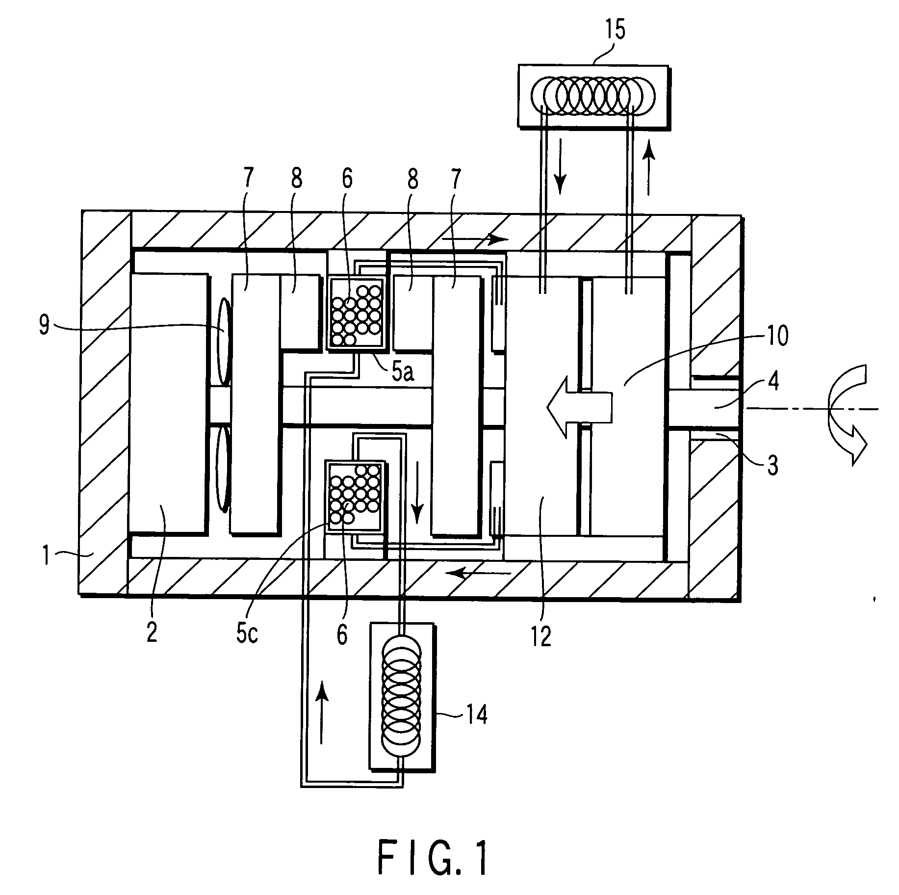
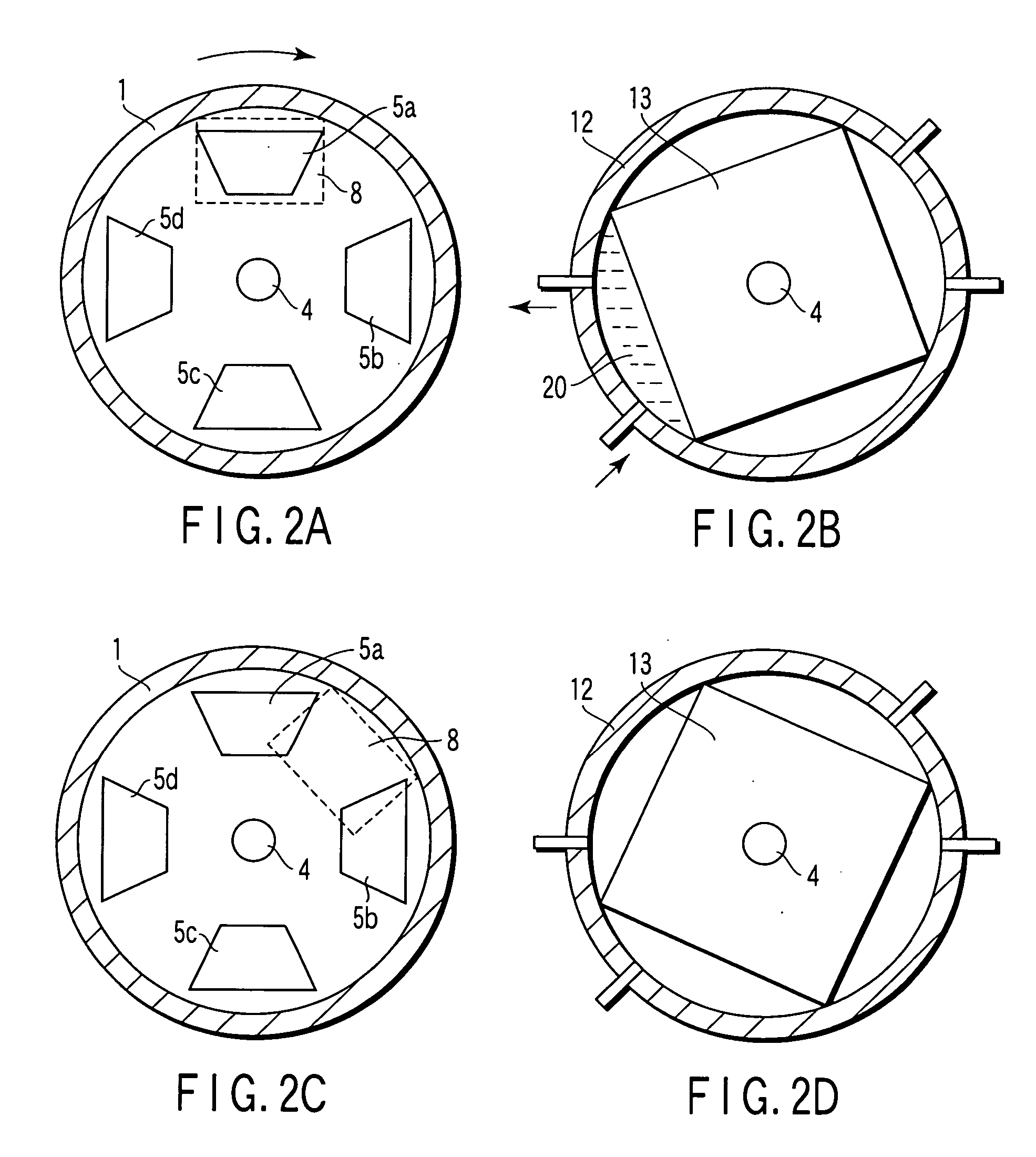
[0021]FIG. 1 is a longitudinal sectional view of a magnetic refrigerator according to an embodiment of the invention. FIG. 2A is a plane view showing the positional relationship between a heat exchanger and a permanent magnet at a certain angle of rotation. FIG. 2B is a plane view showing the positional relationship between a rotor and an inlet and outlet for the refrigerant of a rotary refrigerant control valve at a certain angle of rotation. FIG. 2C is a plane view showing the positional relationship between a heat exchanger and a permanent magnet at another angle of rotation. FIG. 2D is a plane view showing the positional relationship between a rotor and an inlet and outlet for the refrigerant of a rotary refrigerant control valve at another angle of rotation. FIG. 3 is a plane view showing the structure of a refrigerant circulation...


PUM


Abstract

A magnetic refrigerator has a housing, heat exchangers filled with magnetic particles having a magnetocaloric effect, a rotary drive, a rotating shaft, a magnetic field generator fixed to the rotating shaft which applies a magnetic field to or eliminates a magnetic field from the magnetic particles in the heat exchangers following rotation of the rotating shaft, a refrigerant pump which circulates the refrigerant following rotation of the rotating shaft, a rotary refrigerant control valve which controls supply of the refrigerant to and discharge of the refrigerant from the heat exchangers following rotation of the rotating shaft, and a refrigerant circuit. The magnetic field generator and the rotary refrigerant control valve are configured to synchronize application of the magnetic field to or elimination of the magnetic field from the magnetic particles with supply of the refrigerant to or discharge of the refrigerant from the heat exchangers.

Description

CROSS-REFERENCE TO RELATED APPLICATIONS [0001] This application is based upon and claims the benefit of priority from the prior Japanese Patent Application No. 2005-100309, filed Mar. 31, 2005, the entire contents of which are incorporated herein by reference. BACKGROUND OF THE INVENTION [0002] 1. Field of the Invention [0003] The present invention relates to a magnetic refrigerator using a magnetic material having a magnetocaloric effect. [0004] 2. Description of the Related Art [0005] The present refrigeration technique in a room temperature range related closely to human daily life, such as a refrigerator, a freezer and an air conditioner utilizes a vapor compression cycle. However, the refrigeration technique based on the vapor compression cycle has a serious problem of environmental disruption caused by emission of chlorofluorocarbons. Chlorofluorocarbon alternatives seem to have a bad influence on the environment. Under the circumstances, efforts have been taken to protect the...

Claims


Application Information

Patent Timeline
IPC IPC(8): F25B21/00
CPCF25B21/00Y02B30/66F25B2321/0022Y02B30/00
Inventor KOBAYASHI, TADAHIKOSAITO, AKIKOTSUJI, HIDEYUKI
Owner KK TOSHIBA
Learn More