Variable displacement radial piston pump

a radial piston, variable technology, applied in the direction of pump control, positive displacement liquid engine, machine/engine, etc., can solve the problems of excessive hotness, weight and expense of the fuel system, and increase complexity, weight and expens

Active Publication Date: 2006-10-05
EATON INTELLIGENT POWER LIMITED
View PDF13 Cites 17 Cited by
  • Summary
  • Abstract
  • Description
  • Claims
  • Application Information

AI Technical Summary

Benefits of technology

[0010] A cylinder block is mounted for rotation within the aperture of the cylinder ring and has a plurality of radially extending cylinders. Each radially extending cylinder has a port, which selectively communicates with the fluid inlet passage and a fluid outlet passage as the cylinder block rotates. A plurality of cylinders pistons, which are free to slide, are received within the plurality of cylinders and engage the cam surface of the cylinder ring. An actuator is operably coupled to produce movement of the cylinder ring, which alters the spatial relationship between the cylinder ring and the cylinder block to vary the distance that the pistons move within the cylinders.
[0011] The magnitude of fluid flow produced by the pump is directly related to the stroke of the pistons, (amount of movement) within the cylinders as the cylinder block rotates. Therefore, varying the position of the cylinder ring in relation to the cylinder block controls the magnitude of fluid flow.

Problems solved by technology

However, circulation in the bypass circuit heats the fuel, which may become excessively hot, especially when a relatively low flow fuel flow rate is demanded by the engine.
This adds complexity, weight and expense to the fuel system.

Method used


Image

  • Variable displacement radial piston pump
  • Variable displacement radial piston pump
  • Variable displacement radial piston pump

Examples


Embodiment Construction

[0014] The present invention is being described in the context of a fuel pump for a gas turbine engine for an aircraft, however it should be appreciated that the novel concepts of this invention have application to a wide variety of pumps for other fluids and equipment.

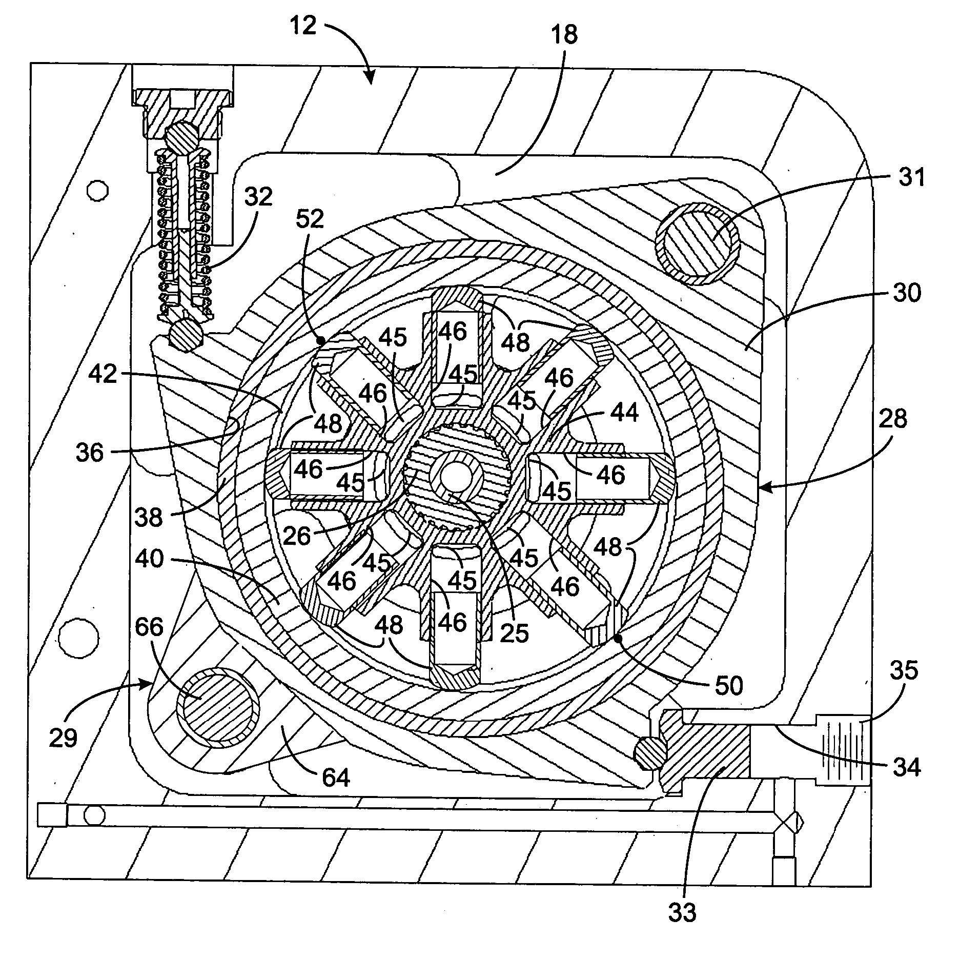
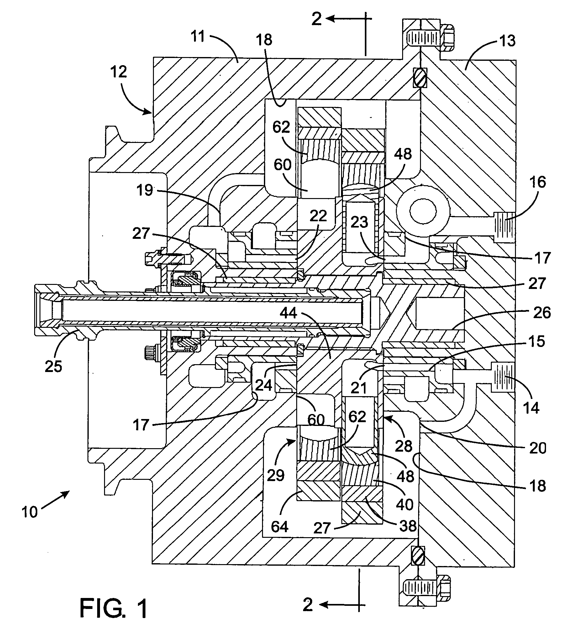
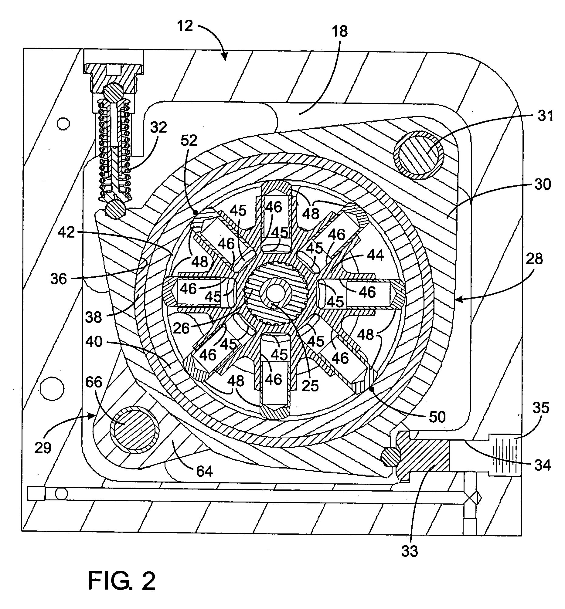
[0015] With reference initially to FIG. 1, a pump 10 has a housing 12 formed by first and second segments 11 and 13 that are secured together by bolts or other suitable fasteners with a seal there between. An internal cavity 18 is formed between the two housing segments. A drive shaft 25 projects into the housing 12 through an aperture on one side and engages a pump shaft 26 that extends across the internal cavity 18 and is rotatably mounted in the housing by bearings or bushings 27. The drive shaft 25 conveys power from the engine gearbox to the pump shaft 26 which is mounted between first and second pump sections 28 and 29 within the housing. Note that the walls of the internal cavity 18 project closer together in ...


PUM


Abstract

A radial pump has a housing with a cylinder ring is pivotally mounted therein. The cylinder ring has a circular aperture within which a cam surface is formed. A cylinder block rotates within the cylinder ring aperture and has a plurality of radially extending cylinders each having port which selectively communicates with a fluid inlet and a fluid outlet as the cylinder block rotates. A plurality of pistons is slideably received within the plurality of cylinders and engages the cam surface. An actuator operably coupled to produce movement of the cylinder ring, which alters the spatial relationship between the cylinder ring and the cylinder block to vary the amount that the pistons move within the cylinders. The amount of movement of the pistons within the cylinders is directly related to the magnitude of fluid flow delivered by the pump and moving the cylinder ring thereby controls the fluid flow. Rotation of the bearing ring produces less torsional drag (parasitic horsepower loss) than the sliding motion of the pistons on a stationary ring, which allows for increasing speed of operation and less performance losses.

Description

CROSS-REFERENCE TO RELATED APPLICATIONS [0001] Not Applicable STATEMENT REGARDING FEDERALLY SPONSORED RESEARCH OR DEVELOPMENT [0002] Not Applicable BACKGROUND OF THE INVENTION [0003] 1. Field of the Invention [0004] The present invention relates to rotary pump, and more specifically to high speed piston pumps having variable displacement, such as for use in aircraft fuel and hydraulic systems for pumping, metering and control for aircraft systems including engines. [0005] 2. Description of the Related Art [0006] Fixed displacement pumps are conventionally employed as fuel pumps for aircraft turbine engines. Such pumps must be capable of providing sufficient fuel pressure and flow to the engine over a wide range of operating speeds from starting to full throttle operation. Therefore, a common practice is for the pump to produce a relatively high output flow rate at all times. The fuel system meters the pump output flow to supply fuel at a rate that is actually required by the engine....

Claims


Application Information

Patent Timeline
Patent Type & Authority Applications(United States)
IPC IPC(8): F04B1/06
CPCF04B1/07F04B1/1077F04B1/1071
Inventor HANSEN, LOWELL DEAN
Owner EATON INTELLIGENT POWER LIMITED
Why Eureka
Try Eureka