Umbrella base clamp

Active Publication Date: 2006-10-19
MA
View PDF27 Cites 9 Cited by
  • Summary
  • Abstract
  • Description
  • Claims
  • Application Information

AI Technical Summary

Benefits of technology

[0007] It will be appreciated that there is a need and desire for securing structures or mechanisms for umbrella base and umbrella pole connections that inhibit or reduce unwanted rotational movement therebetween once a connection is made. As umbrellas are often consumer items, such a securing structure or mechanism advantageou

Problems solved by technology

Rotation may result in damage or dislodgement of the umbrella.
As mentioned, unwanted rotation of the umbrella

Method used


Image

  • Umbrella base clamp
  • Umbrella base clamp
  • Umbrella base clamp

Examples


Embodiment Construction

[0030] Reference will now be made to the drawings wherein like reference numerals refer to like parts throughout.

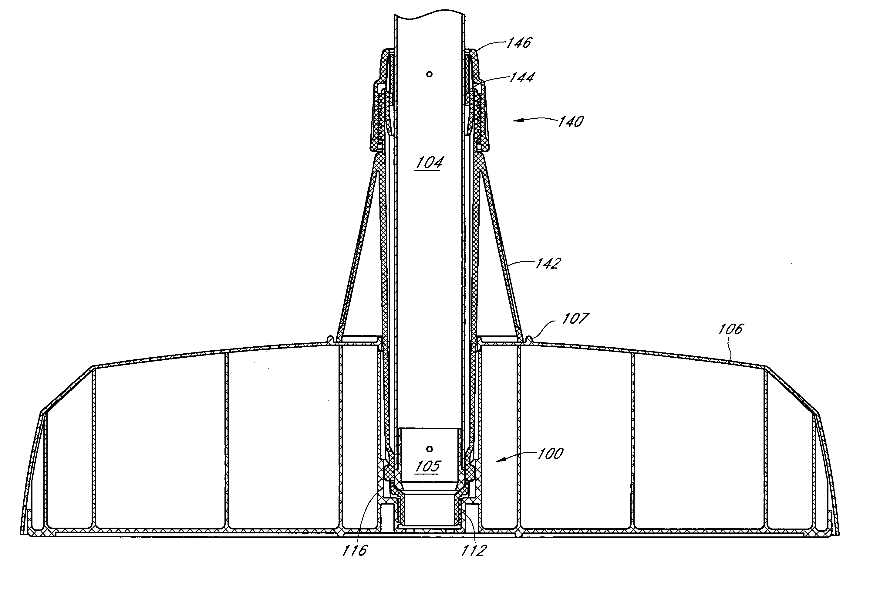
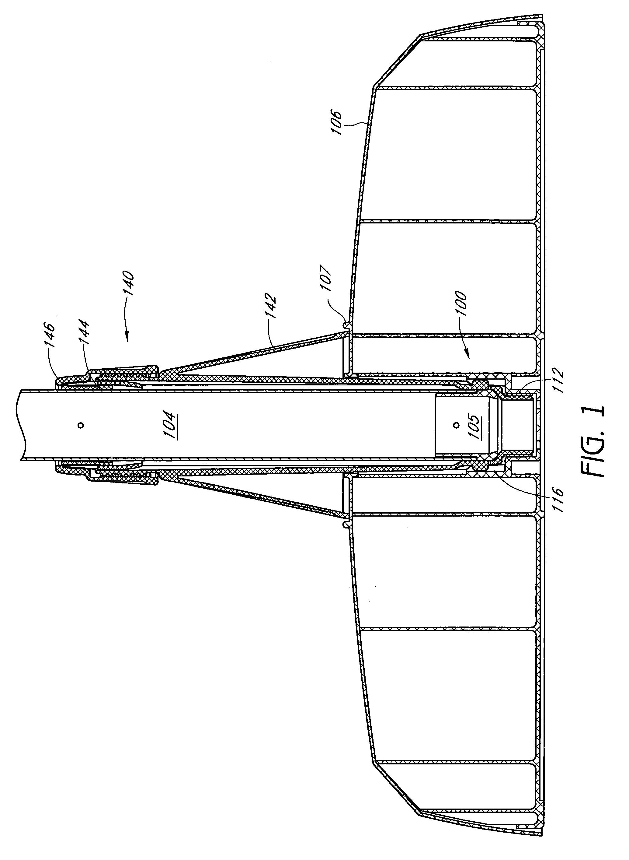
[0031]FIG. 1 illustrates a side section view of one embodiment of an umbrella base clamp assembly 100. The umbrella base clamp 100 is configured to secure an umbrella pole 104 to an umbrella base 106 to restrict or inhibit unwanted rotational movement therebetween. The umbrella pole 104 can take any suitable form. In one embodiment, the pole 104 is a generally hollow structure that can have a cap 105 positioned at a lower end thereof. The cap 105 can be made of any suitable material, e.g., aluminum or another metal or a plastic material. In one embodiment, the umbrella base clamp assembly 100 comprises a first clamp assembly which can cooperate with a second umbrella base clamp assembly such as the assembly 140 or the assembly 140′ which will be described in greater detail below.

[0032] The umbrella base 106 is configured to receive a material to increase the weight ther...


PUM


Abstract

A base assembly is provided that includes a base and a coupler. The coupler includes a sleeve for receiving an umbrella pole, a lower portion comprising a side surface, and a locking member coupled with the side surface. The locking member is configured to move toward or away from a longitudinal axis of the sleeve such that the locking member engages the base to prevent rotation of the coupler relative to the base.

Description

CROSS-REFERENCE TO RELATED APPLICATIONS [0001] This application claims priority under 35 U.S.C. §119(a) to Utility Model No. 200520039686.1, filed Feb. 18, 2005 in the People's Republic of China, which is hereby expressly incorporated herein by reference in its entirety. BACKGROUND OF THE INVENTION [0002] 1. Field of the Invention [0003] This application relates to the umbrellas and more particularly to clamp assemblies for securing an umbrella pole to an umbrella base and to secure a rotational orientation therebetween. [0004] 2. Description of the Related Art [0005] Umbrellas are widely used to provide shade and other weather protection and are frequently employed in an outdoor or patio type setting. Many umbrellas include a deployable canopy portion which is supported by an elongate umbrella pole. In many applications, it is desired to mount or support the pole on an umbrella base. An umbrella pole can be permanently affixed to an umbrella base or can be attached in a removable o...

Claims


Application Information

Patent Timeline
IPC IPC(8): F16M13/00
CPCA45B2023/0012Y10T403/32426E04H12/2246E04H12/2238
Inventor MA, OLIVER JOEN-AN
Owner MA
Why Eureka
Try Eureka