[0003] The object of the present invention consists in developing the electronic ballast mentioned initially such that more reliable EoL detection is thus made possible.
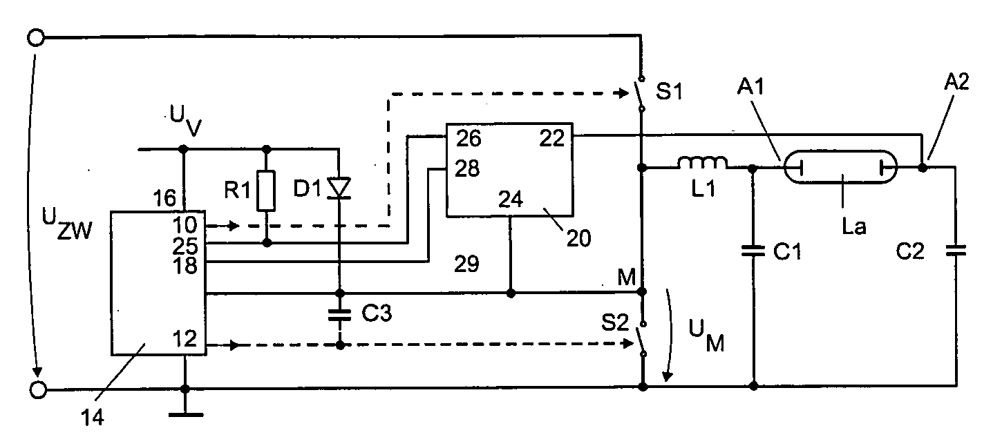
[0005] One particularly advantageous embodiment is therefore characterized by the fact that the DC
voltage reference potential for the signal evaluation unit is essentially the potential of the center point of the half-bridge circuit. In the case of a “floating” EoL detection dimensioned in this manner, the DC voltage useful signal is accordingly not superimposed by any interfering DC voltage. The measurement error owing to component tolerances is therefore minimal, and the reliability of the result is maximal.
[0006] One preferred embodiment also comprises a
control unit for the purpose of driving the first switch and the second switch, the
control unit having a disconnection or regulation input, which is coupled to the signal evaluation unit, the
control unit and the signal evaluation unit being designed to interact such that, in the event of a difference between the DC voltage component of the signals at the two inputs of the signal evaluation unit which is above a predeterminable
limit value, the signal evaluation unit drives the control unit via the disconnection or regulation input such that no driving of the first switch and / or the second switch is carried out or the first switch and / or the second switch are driven such that the output power of the electronic ballast is reduced. Owing to this measure, damage to the electronic ballast is reliably prevented when an EoL situation is detected. When continuing to operate a lamp in an EoL situation, there is also the risk of the lamp overheating, which may result in breakage or melting of the lamp and thus in people in the environment of the lamp being endangered.
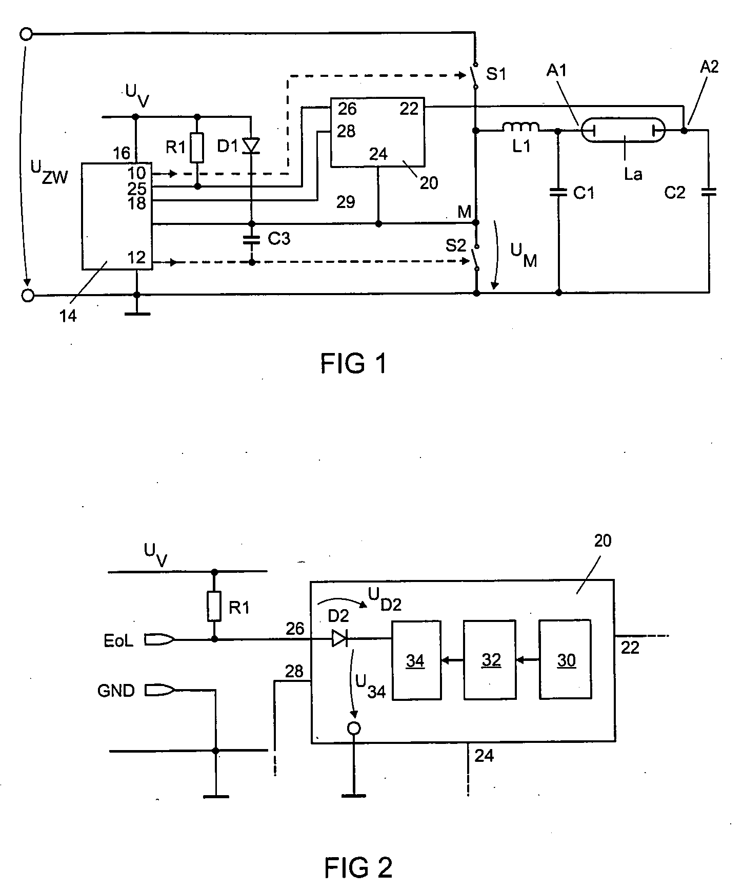
[0007] In one further preferred embodiment, the control unit has a supply voltage connection and is connected to the ground potential as a DC
voltage reference potential. The signal evaluation unit comprises a latch and is designed to activate the latch if the difference in the DC voltage component of the signals at the two inputs of the signal evaluation unit is above a predeterminable
limit value, the output of the latch being coupled to the supply voltage connection of the control unit and / or the signal evaluation unit via the series circuit comprising a
diode and a nonreactive
resistor. In this variant, the signal evaluation unit is in the form of an active circuit, the supply voltage of the control unit and / or the signal evaluation unit, which is generally of the
order of magnitude of 15 V and thus of the
order of magnitude of EoL DC voltage useful signal, being used for evaluation purposes in a skillful manner. If the output signal of the signal evaluation unit is combined in this manner with the supply voltage of the control unit and / or the signal evaluation unit, the signal which can be tapped off at the connection point between the
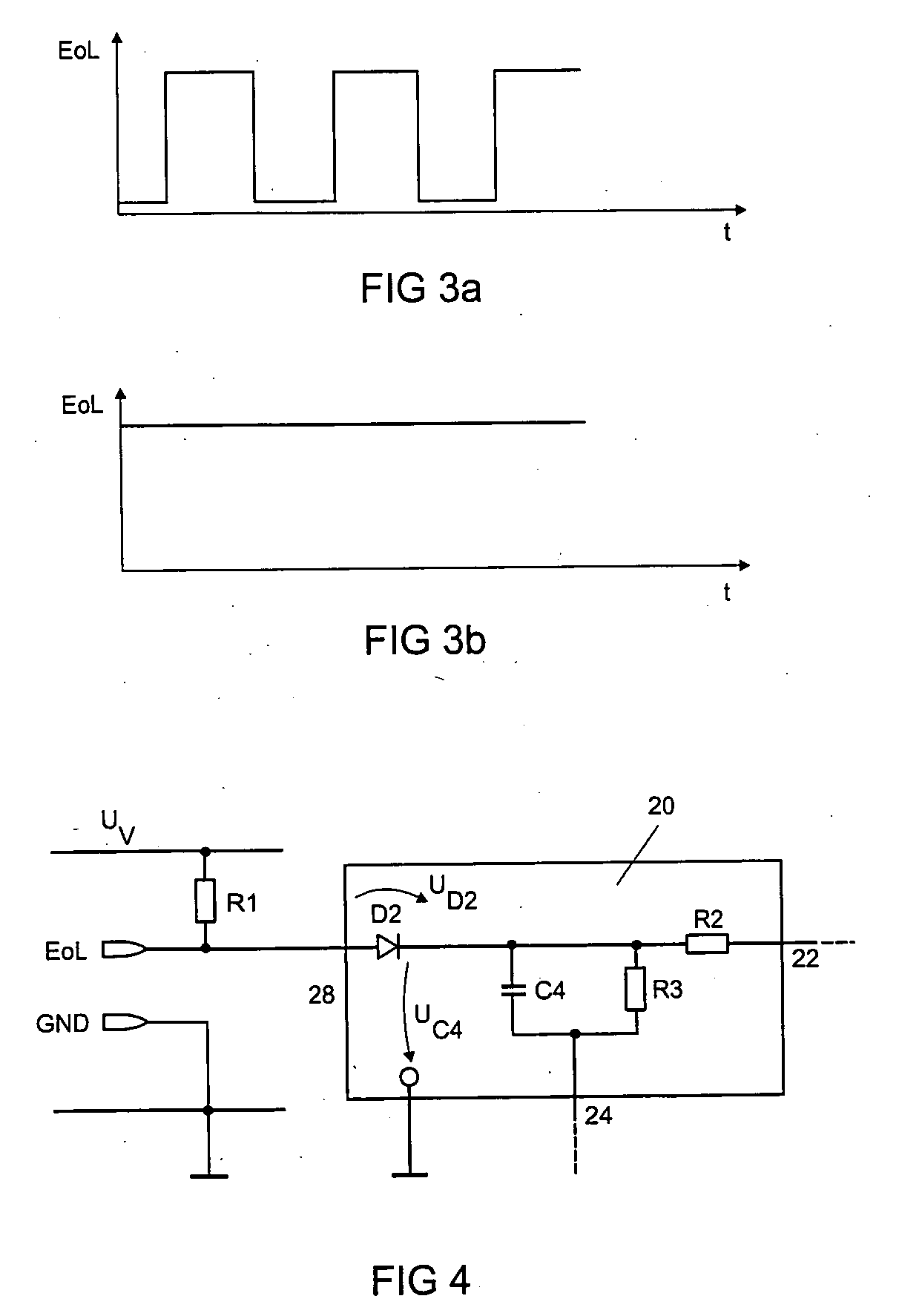
diode and the nonreactive
resistor, the so-called EoL signal, is characterized by the fact that, in the case of an intact lamp, it is a signal having a constant amplitude, whereas this signal is a square-wave signal in the case of a defective lamp. The difference between the DC voltage signal and the square-wave signal can be evaluated in a very simple manner. As a result, it is possible to implement extremely cost-effective and reliable EoL detection.
[0008] In the case of an implementation of the signal evaluation unit using passive components, the signal evaluation unit has a
capacitor which is arranged such that it has a
voltage drop across it which corresponds to the difference in the DC voltage component of the signals at the two inputs of the signal evaluation unit, the
capacitor being coupled to the supply voltage connection of the control unit via the series circuit comprising a
diode and a nonreactive
resistor. If, in turn, the so-called EoL signal at the connection point between the diode and the nonreactive resistor is taken into consideration here, it is now possible for an intact lamp to be established by means of a positive square-wave signal. A defective lamp is characterized by a signal having a constant amplitude, in the case of a positive DC voltage useful signal, while an EoL signal having a square-
wave shape is produced in the case of a negative DC voltage useful signal, but this also has negative amplitude components, in contrast to the square-wave signal in the case of an intact lamp. These three signals can also be differentiated from one another in a very simple manner and make possible cost-effective and reliable EoL detection of a lamp.

