Electronic ballast for a lamp

a technology of electronic ballast and lamp, which is applied in the field of electronic ballast for lamps, can solve the problems of minimal error owing to component tolerance, small measurement error, and maximum reliability of results, and achieve the effect of reliable eol detection

Active Publication Date: 2008-09-02
PATENT TREUHAND GESELLSCHAFT FUER ELECTRIC GLUEHLAMPEN M B H
View PDF5 Cites 0 Cited by
  • Summary
  • Abstract
  • Description
  • Claims
  • Application Information

AI Technical Summary

Benefits of technology

[0003]The object of the present invention consists in developing the electronic ballast mentioned initially such that more reliable EoL detection is thus made possible.
[0005]One particularly advantageous embodiment is therefore characterized by the fact that the DC voltage reference potential for the signal evaluation unit is essentially the potential of the center point of the half-bridge circuit. In the case of a “floating” EoL detection dimensioned in this manner, the DC voltage useful signal is accordingly not superimposed by any interfering DC voltage. The measurement error owing to component tolerances is therefore minimal, and the reliability of the result is maximal.
[0006]One preferred embodiment also comprises a control unit for the purpose of driving the first switch and the second switch, the control unit having a disconnection or regulation input, which is coupled to the signal evaluation unit, the control unit and the signal evaluation unit being designed to interact such that, in the event of a difference between the DC voltage component of the signals at the two inputs of the signal evaluation unit which is above a predeterminable limit value, the signal evaluation unit drives the control unit via the disconnection or regulation input such that no driving of the first switch and / or the second switch is carried out or the first switch and / or the second switch are driven such that the output power of the electronic ballast is reduced. Owing to this measure, damage to the electronic ballast is reliably prevented when an EoL situation is detected. When continuing to operate a lamp in an EoL situation, there is also the risk of the lamp overheating, which may result in breakage or melting of the lamp and thus in people in the environment of the lamp being endangered.
[0007]In one further preferred embodiment, the control unit has a supply voltage connection and is connected to the ground potential as a DC voltage reference potential. The signal evaluation unit comprises a latch and is designed to activate the latch if the difference in the DC voltage component of the signals at the two inputs of the signal evaluation unit is above a predeterminable limit value, the output of the latch being coupled to the supply voltage connection of the control unit and / or the signal evaluation unit via the series circuit comprising a diode and a nonreactive resistor. In this variant, the signal evaluation unit is in the form of an active circuit, the supply voltage of the control unit and / or the signal evaluation unit, which is generally of the order of magnitude of 15 V and thus of the order of magnitude of EoL DC voltage useful signal, being used for evaluation purposes in a skillful manner. If the output signal of the signal evaluation unit is combined in this manner with the supply voltage of the control unit and / or the signal evaluation unit, the signal which can be tapped off at the connection point between the diode and the nonreactive resistor, the so-called EoL signal, is characterized by the fact that, in the case of an intact lamp, it is a signal having a constant amplitude, whereas this signal is a square-wave signal in the case of a defective lamp. The difference between the DC voltage signal and the square-wave signal can be evaluated in a very simple manner. As a result, it is possible to implement extremely cost-effective and reliable EoL detection.
[0008]In the case of an implementation of the signal evaluation unit using passive components, the signal evaluation unit has a capacitor which is arranged such that it has a voltage drop across it which corresponds to the difference in the DC voltage component of the signals at the two inputs of the signal evaluation unit, the capacitor being coupled to the supply voltage connection of the control unit via the series circuit comprising a diode and a nonreactive resistor. If, in turn, the so-called EoL signal at the connection point between the diode and the nonreactive resistor is taken into consideration here, it is now possible for an intact lamp to be established by means of a positive square-wave signal. A defective lamp is characterized by a signal having a constant amplitude, in the case of a positive DC voltage useful signal, while an EoL signal having a square-wave shape is produced in the case of a negative DC voltage useful signal, but this also has negative amplitude components, in contrast to the square-wave signal in the case of an intact lamp. These three signals can also be differentiated from one another in a very simple manner and make possible cost-effective and reliable EoL detection of a lamp.

Problems solved by technology

Accordingly, the smaller the DC voltage component which is superimposed on the DC voltage useful signal, the smaller the error in the measurement result.
The measurement error owing to component tolerances is therefore minimal, and the reliability of the result is maximal.
When continuing to operate a lamp in an EoL situation, there is also the risk of the lamp overheating, which may result in breakage or melting of the lamp and thus in people in the environment of the lamp being endangered.

Method used


Image

  • Electronic ballast for a lamp
  • Electronic ballast for a lamp
  • Electronic ballast for a lamp

Examples


Embodiment Construction

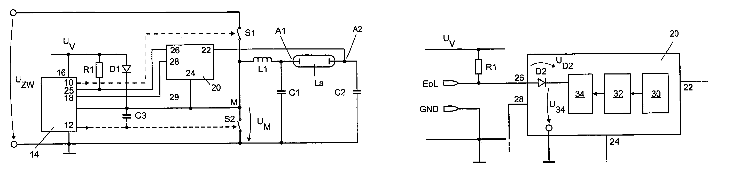
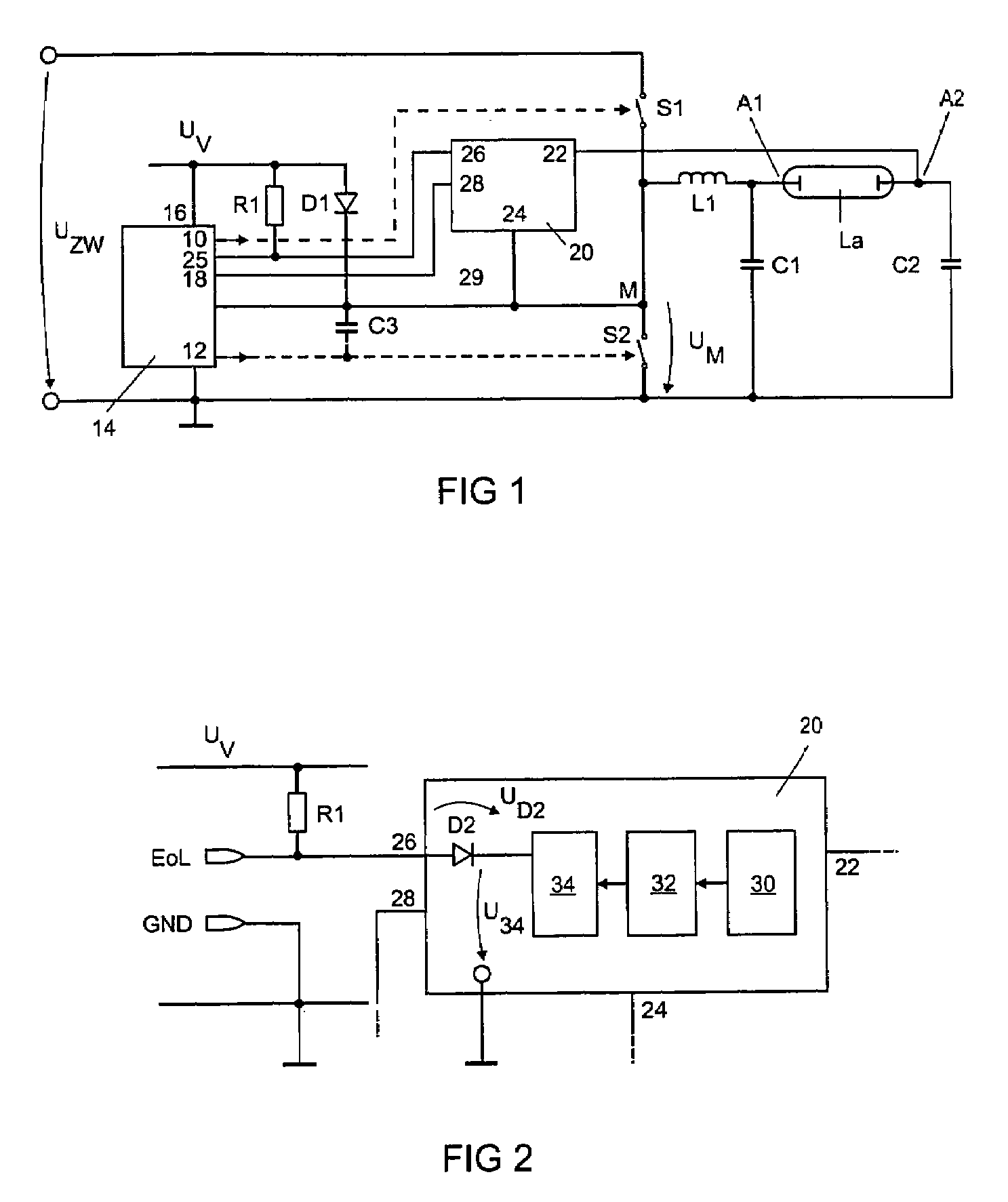
[0021]FIG. 1 shows a schematic illustration of an electronic ballast according to the invention for a lamp. Since such electronic ballasts are generally known, only the part relevant to the invention is illustrated schematically for reasons of clarity. In this case, a first switch S1 and a second switch S2, which between them define a center point M, have the so-called intermediate circuit voltage UZW applied to them. The center point M is coupled to a first connection A1 of a lamp La via an inductance L1. Moreover, the connection A1 is connected to the ground potential via a coupling capacitor C1. The second connection A2 for the lamp La is coupled to the ground potential via a coupling capacitor C2. An inductance L1 is coupled between the center point M of the half-bridge circuit and the first connection A1 for a lamp. The electronic ballast comprises a control unit 14, which drives the switch S1 via an output 10 and the switch S2 via an output 12 in a known manner in opposition u...


PUM


Abstract

An electronic ballast for a lamp having a bridge circuit, includes at least one first switch and a second switch coupled between a connection for a supply voltage and a connection for a ground potential, a center point of the bridge circuit between the first switch and second switches; a first and a second connection for a lamp the first connection coupled to the center point; and a signal evaluation unit. The evaluation unit includes a first input coupled to a signal which is at the DC voltage level of the first connection, and second input coupled to a signal which is at the DC voltage level of the second connection, the DC voltage reference potential for the evaluation unit being designed to be variable within a value range which is greater than or equal to the ground potential and is less than or equal to the supply voltage potential.

Description

FIELD OF THE INVENTION[0001]The present invention relates to an electronic ballast for a lamp, in particular an electronic ballast having a bridge circuit, which comprises at least one first switch and a second switch which are coupled between a connection for a supply voltage and a connection for a ground potential, a center point of the bridge circuit being defined between the first switch and the second switch, a first connection and a second connection for a lamp, the first connection being coupled to the center point of the bridge circuit via an inductance, and a signal evaluation unit, the signal evaluation unit comprising a first input and a second input, the first input being coupled to a signal which is at the DC voltage level of the first connection for the lamp, and the second input being coupled to a signal which is at the DC voltage level of the second connection for the lamp.BACKGROUND OF THE INVENTION[0002]Such an electronic ballast for a lamp is known. In this case, ...

Claims


Application Information

Patent Timeline
Patent Type & Authority Patents(United States)
IPC IPC(8): H05B37/00
CPCH05B41/2855Y10S315/05H05B41/26H05B41/14
Inventor HECKMANN, MARKUS
Owner PATENT TREUHAND GESELLSCHAFT FUER ELECTRIC GLUEHLAMPEN M B H
Why Eureka
Try Eureka