Inverter control apparatus and inverter control method

a control apparatus and inverter technology, applied in the direction of electric controllers, electronic commutators, dynamo-electric converter control, etc., can solve the problems of reducing the accuracy of the a/d-converter motor current, affecting the accuracy of the a/d conversion, and not uniformly ensuring the time period for the a/d conversion of all phases. , to achieve the effect of high reliability, preventing abnormal overheating, and high reliability of judgmen

Inactive Publication Date: 2006-05-23
NIPPON YUSOKI
View PDF66 Cites 47 Cited by
  • Summary
  • Abstract
  • Description
  • Claims
  • Application Information

AI Technical Summary

Benefits of technology

[0020]It is a further object of the invention to stably check normality / abnormality of each switching element, thereby obtaining a highly reliable judgment result.
[0055]According to the invention, the interrupt signals are always generated at fixed timings, a relatively long time period can be ensured for the judgment of normality / abnormality of the switching elements, and the judgment can be conducted in a state where the elements are stabilized. Therefore, it is possible to obtain a highly reliable judgment result.

Problems solved by technology

In the case of (1), in the conventional system in which a single triangular wave carrier signal is used, the amount of data which can be obtained in one cycle of the carrier signal is restricted, and hence the improvement of the accuracy of the A / D conversion is limited.
However, JP-A-2002-27763 discloses nothing about the problems and method for solving them.
Therefore, there is a possibility that the A / D conversion is conducted in an unstable condition where, for example, the switching element is not completely set to the ON state, thereby causing a problem in that the accuracy of the A / D-converted motor current is lowered.
Therefore, also the time period which can be consumed for the A / D conversion of the motor current of each phase is not constant, and the time period for the A / D conversion is not uniformly ensured for the motor currents of all the phases.
Consequently, a motor current value which is A / D-converted in a period where the interval between the interrupt signals is short has low reliability.
When the motor is feedback controlled with using such a motor current value, there is a problem in that the accuracy of the motor control is lowered.

Method used


Image

  • Inverter control apparatus and inverter control method
  • Inverter control apparatus and inverter control method
  • Inverter control apparatus and inverter control method

Examples


first embodiment

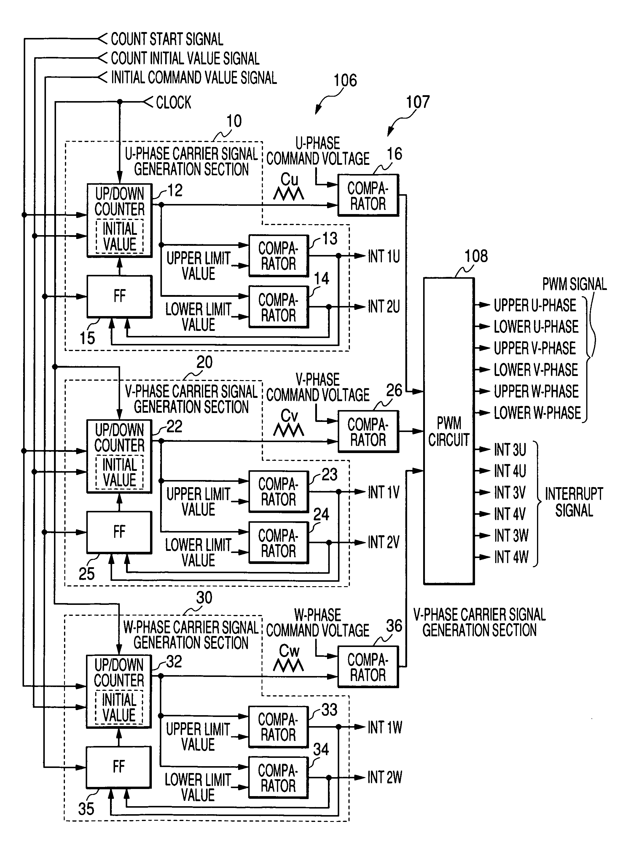
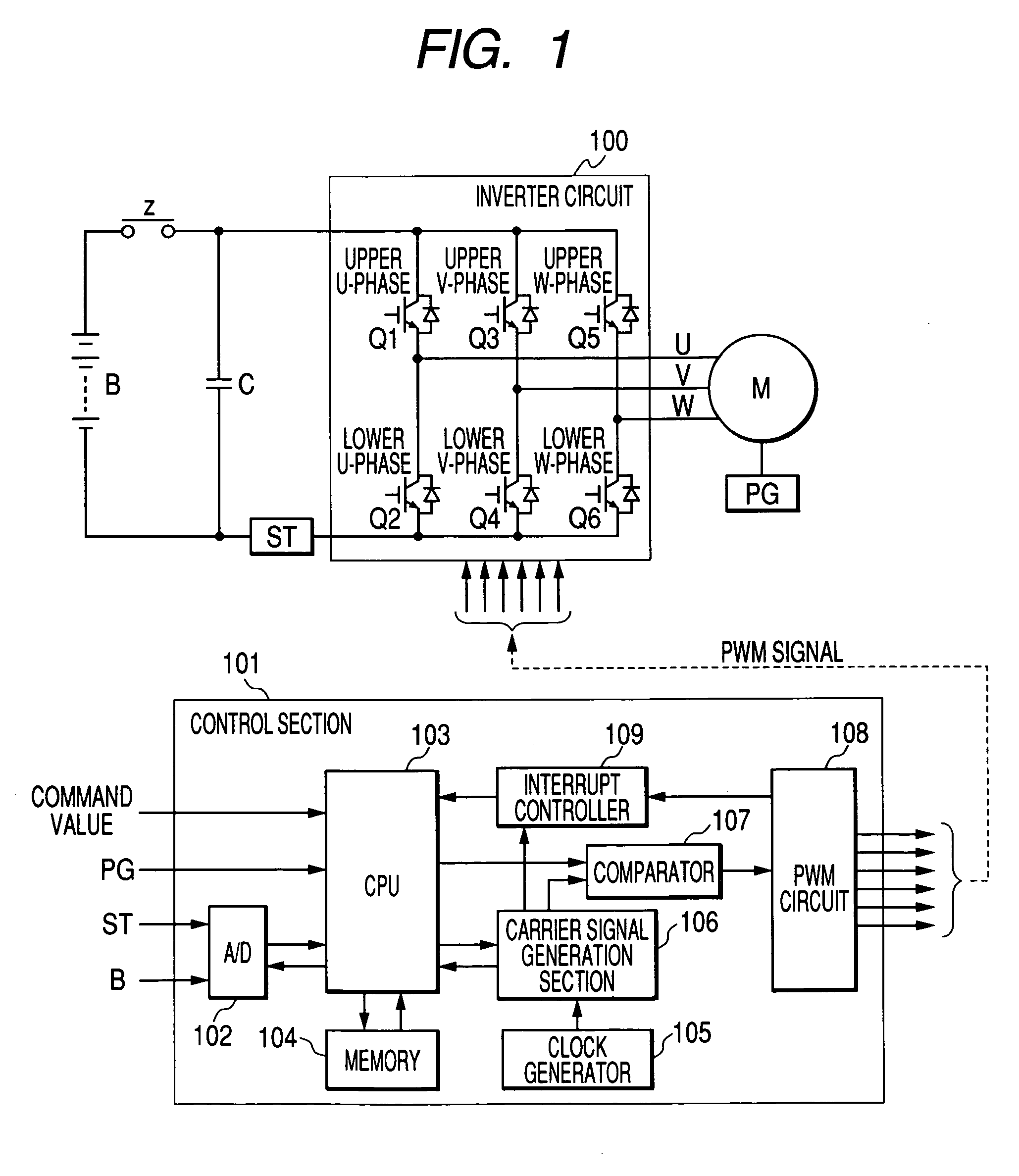
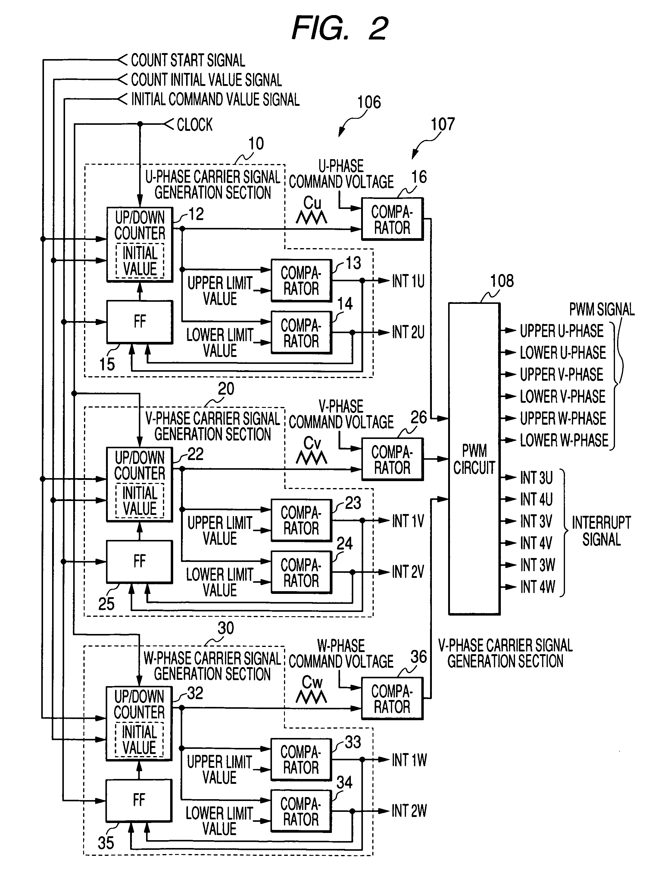
[0079]FIG. 1 shows an inverter control apparatus of the invention. In the drawing, B denotes a battery. A power is supplied from the battery B to a motor M via a contactor Z and an inverter circuit 100. The motor M is a three-phase induction motor which is mounted on, for example, a forklift. The contactor Z is configured by contacts of an electromagnetic contactor. In the drawing, C denotes a capacitor which is connected between power lines, ST denotes a shunt which is used for detecting the current flowing through the motor M, which is configured by resistors, and which corresponds to the current detection method in the invention, and PG denotes a pulse generator which is used for detecting the revolution of the motor M, and which is configured by a known rotary encoder disposed on the rotary shaft of the motor M.

[0080]The inverter circuit 100 is a known circuit which converts the DC power source of the battery B to an AC power source to drive the motor M, and which is configured ...

second embodiment

[0132]Next, the invention will be described in detail.

[0133]FIG. 17 shows an example of an inverter control apparatus of the second embodiment of the invention. The components which are identical with those in the configuration of the first embodiment shown in FIG. 1 are denoted by the same reference numerals, and their detailed description is omitted.

[0134]In the second embodiment, shunts ST1 to ST3 are disposed in place of the shunt ST in FIG. 1. The shunts ST1 to ST3 detect the currents of the phases (U-phase, V-phase, and W-phase) flowing through the motor M, respectively.

[0135]An inverter circuit 500 is a known circuit which converts the DC power source of the battery B to an AC power source to drive the motor M, and which is configured by the six semiconductor switching elements Q1 to Q6 of U-phase upper, U-phase lower, V-phase upper, V-phase lower, W-phase upper, and W-phase lower. The shunt ST1 is connected in series to the series connection of the switching elements Q1, Q2 ...

third embodiment

[0159]Next, the invention will be described in detail.

[0160]FIG. 20 shows an example of an inverter control apparatus are identical with those in the configurations of the first embodiment shown in FIG. 1 and the second embodiment shown in FIG. 17 are denoted by the same reference numerals, and their detailed description is omitted.

[0161]An inverter circuit 600 is different from the inverter circuit 100 in the first embodiment in that a current sensor 611 which detects the U-phase current Iu, and a current sensor 612 which detects the V-phase current Iv are disposed, and the shunt ST is not disposed. The W-phase current Iw is obtained by adding the U-phase current Iu to the V-phase current Iv. Therefore, a current sensor which detects the W-phase current Iw is not disposed.

[0162]A PWM circuit 608 is different from the PWM circuit 108 in the first embodiment in that the circuit does not send the interrupt signals to an interrupt controller 609.

[0163]To a CPU 603, for example, input a...


PUM


Abstract

An interrupt signal is generated at each of rising timings of PWM signals which are produced on the basis of phase-shifted triangular wave carrier signals for phases, and voltage command values for the phases. At timings of the interrupt signals, A / D conversion of motor currents of the phases detected by a shunt is started. Interrupt signals are also produced at timings of valleys of the triangular wave carrier signals. Additionally, peak interrupt signals and valley interrupt signals are respectively produced at timings of peaks and valleys of triangular wave carrier signals for phases. Based on each of the peak interrupt signals, normality / abnormality of a switching element of an upper side of the phase corresponding to the interrupt signal is checked, and, based on each of the valley interrupt signals, normality / abnormality of a switching element of a lower side of the phase corresponding to the interrupt signal is checked.

Description

BACKGROUND OF THE INVENTION[0001]1. Field of the Invention[0002]The present invention relates to an inverter control apparatus and an inverter control method which are useful for controlling, for example, PWM (Pulse Width Modulation) of a three-phase AC motor.[0003]2. Description of the Related Art[0004]FIG. 10 shows a controller of a common three-phase AC motor operating under PWM control. In the drawing, reference symbol B denotes a battery, and power is supplied from this battery B to a motor M by way of a contactor Z and an inverter circuit 100. For instance, the motor M is a three-phase induction motor mounted on a forklift. The contactor Z is formed from a contact point of a magnetic contactor. In the drawing, reference symbol C denotes a capacitor connected between power lines, and ST denotes a shunt for detecting an electric current flowing into the motor M. The shunt ST is formed from a resistor. Reference symbol PG denotes a pulse generator for detecting the revolutions pe...

Claims


Application Information

Patent Timeline
Patent Type & Authority Patents(United States)
IPC IPC(8): G05B11/28
CPCH02M7/53873H02P29/021H02P27/08H02P29/0241
Inventor KATANAYA, IKUYA
Owner NIPPON YUSOKI
Why Eureka
Try Eureka