Power seat slide apparatus for vehicle

a technology for a power seat and a slide, which is applied in the direction of machine supports, transportation and packaging, and other domestic objects, and can solve the problems that the support bracket b>87/b> may lack the appropriate strength

Inactive Publication Date: 2006-10-26
AISIN SEIKI KK
View PDF5 Cites 17 Cited by
  • Summary
  • Abstract
  • Description
  • Claims
  • Application Information

AI Technical Summary

Problems solved by technology

In consequence, the support bracket 87 may lack appropriate strength.

Method used


Image

  • Power seat slide apparatus for vehicle
  • Power seat slide apparatus for vehicle
  • Power seat slide apparatus for vehicle

Examples


Embodiment Construction

[0022] An embodiment of the present invention will be explained hereinbelow with reference to the attached drawings. According to the embodiment of the present invention, a power seat slide apparatus for a vehicle is mounted to a front seat side of the vehicle such as an automobile, or the like. Further, directions of backward and forward, right and left, and up and down described in the specification are based on the directions of a vehicle seat.

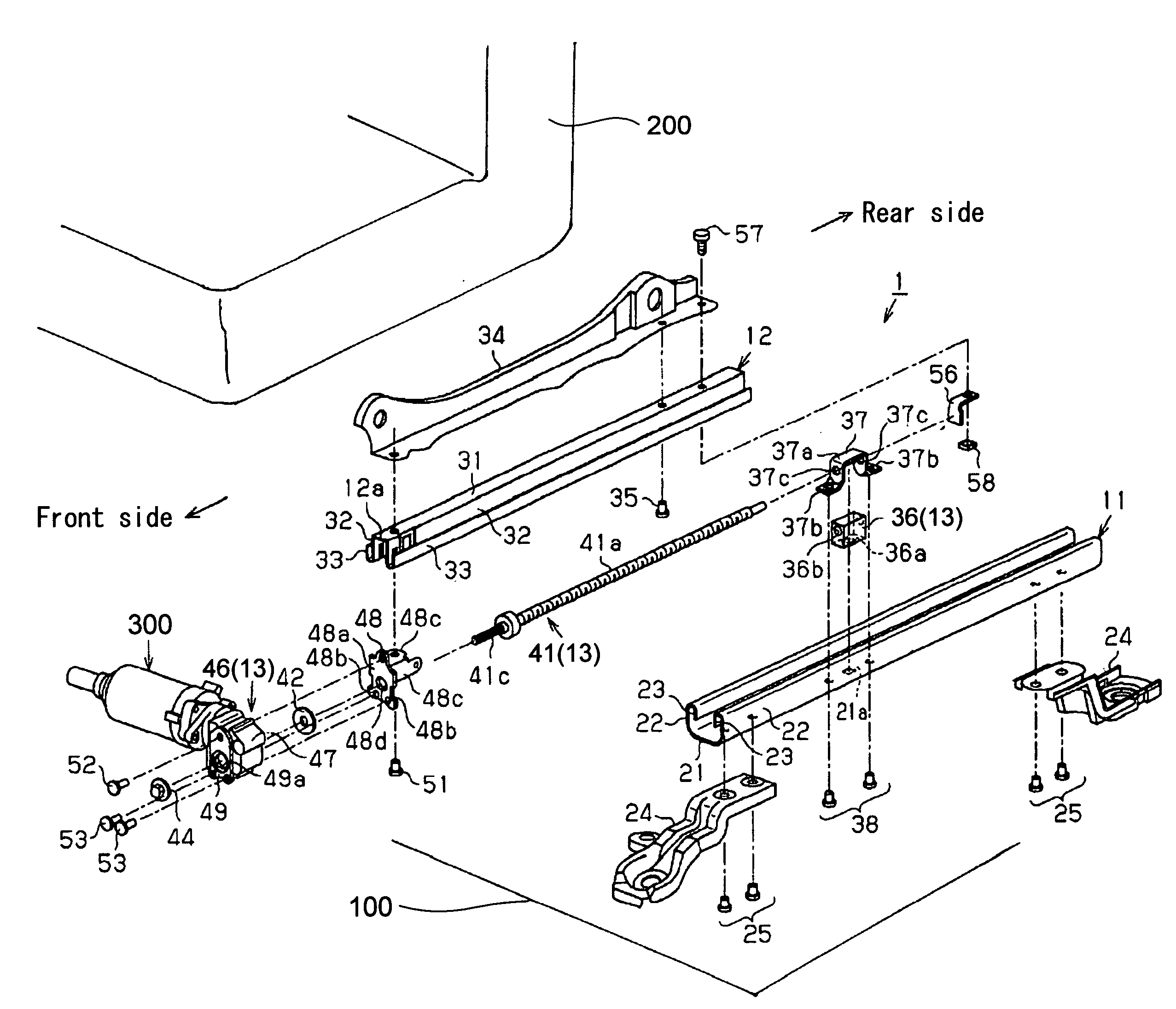
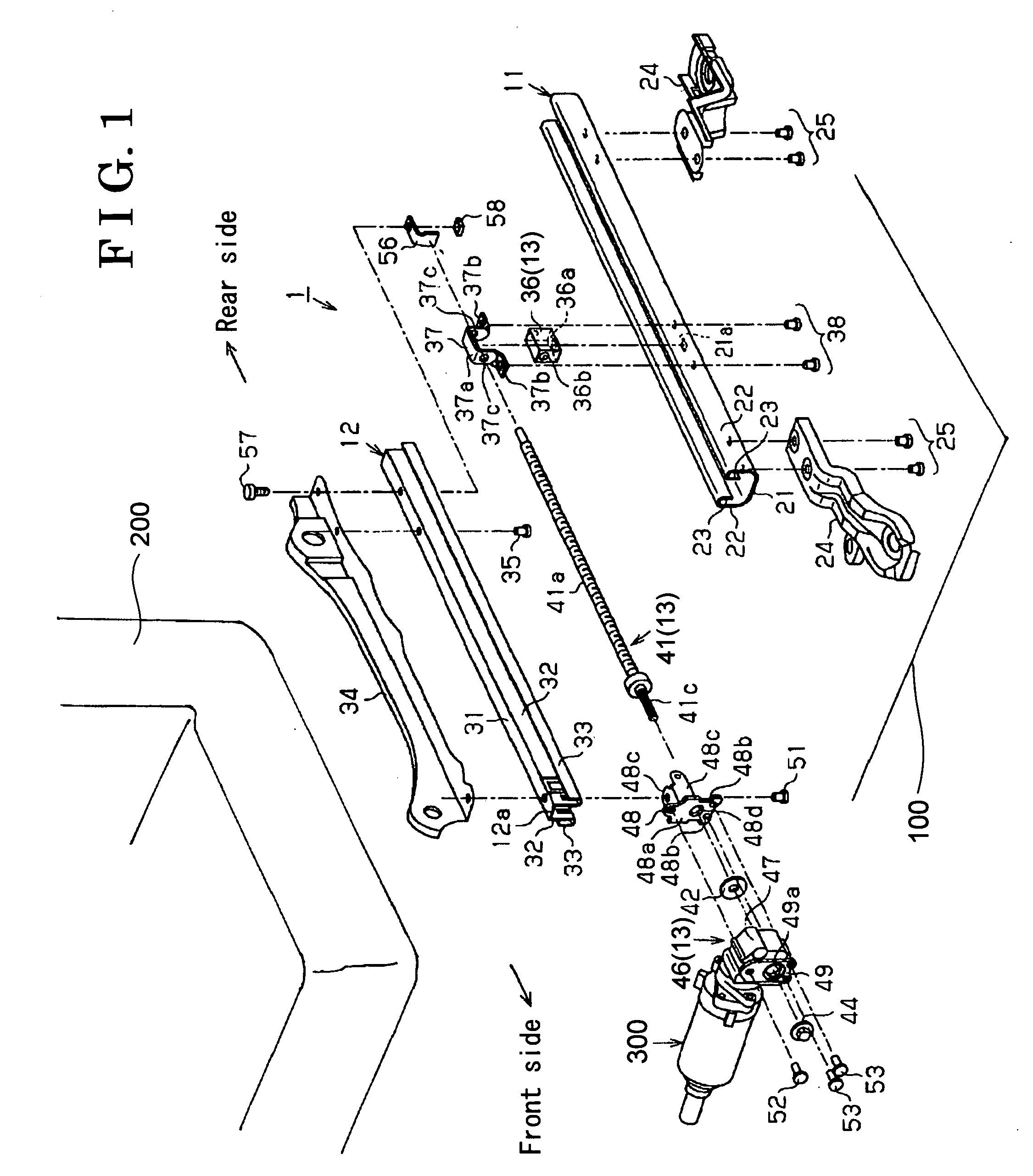
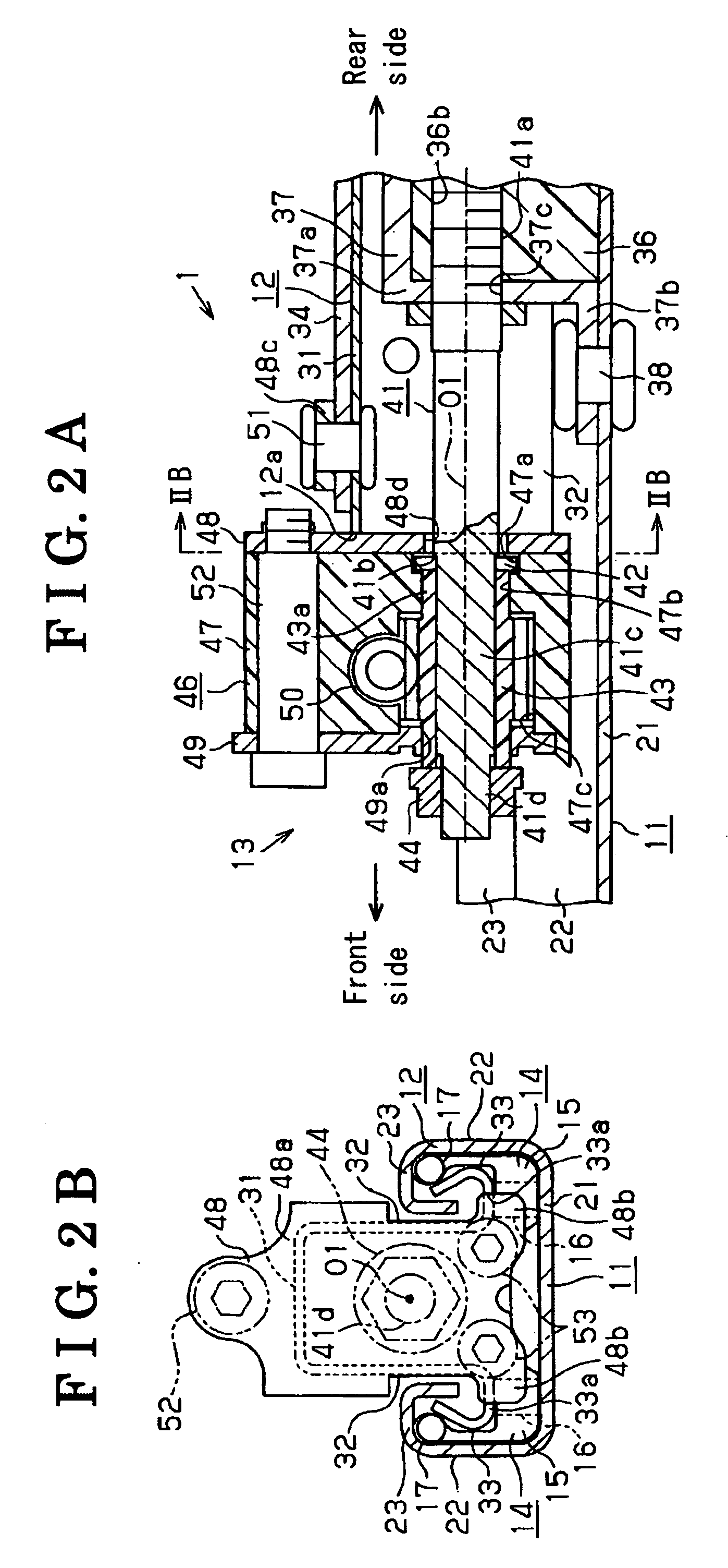
[0023] As illustrated in FIGS. 1-3, the power seat slide apparatus 1 includes a lower rail 11 serving as a first rail, an upper rail 12 serving as a second rail, and an activate mechanism 13.

[0024] The lower rail 11 is formed into a long shape and extends in a backward and forward direction. The lower rail 11 includes a bottom wall portion 21, a pair of first side wall portions 22 extended upward from both sides of the bottom wall portion 21, and a pair of first folded wall portions 23 curved inwardly in a width direction (right and left ...


PUM


Abstract

A power seat slide apparatus for a vehicle includes a first rail adapted to be fixed to a vehicle floor, a second rail adapted to be fixed to a vehicle seat and slidably supported relative to the first rail, a screw shaft screwed to a nut member which is fixed to the first rail, the screw shaft including an end portion and a stepped portion, a washer engaged with the stepped portion of the screw shaft, a gear member to which the end portion of the screw shaft is inserted, a fastening member provided at the end portion of the screw shaft, and a gear box fixed to an end of the second rail. The gear box includes a support bracket, a gear housing, and a plate. The stepped portion of the screw shaft is arranged in such a manner that the washer is connected thereto in the gear housing.

Description

[0001] This application is based on and claims priority under 35 U.S.C. § 119 to Japanese Patent Application 2005-125660, filed on Apr. 22, 2005, the entire content of which is incorporated herein by reference. FIELD OF THE INVENTION [0002] The present invention relates to a power seat slide apparatus for a vehicle. BACKGROUND [0003] JP2001-239861A and JP2002-192996A respectively disclose a power seat slide apparatus for a vehicle, which adjusts a position of a vehicle seat by sliding an upper rail relative to a lower rail by means of a driving force of an electrical drive source. As illustrated in FIGS. 4A-4B, each disclosed power seat slide apparatus for the vehicle includes a lower rail 81, an upper rail 82, a nut member 83, a screw shaft 84, and a gear box 85. The lower rail 81 is fixed to a vehicle floor, the upper rail 82 is slidably supported by the lower rail 81 and supports the vehicle seat, the nut member 83 is fixed to the lower rail 81, the screw shaft 84 is screwed toge...

Claims


Application Information

Patent Timeline
Patent Type & Authority Applications(United States)
IPC IPC(8): F16M13/00
CPCB60N2/067B60N2/0232B60N2/02246
Inventor NAKAMURA, YOSHITAKA
Owner AISIN SEIKI KK
Why Eureka
Try Eureka