Battery cooling structure

Inactive Publication Date: 2010-03-11
HONDA MOTOR CO LTD
View PDF8 Cites 12 Cited by
  • Summary
  • Abstract
  • Description
  • Claims
  • Application Information

AI Technical Summary

Benefits of technology

[0015]Based on the battery cooling structure according to the aspect of the present invention described above, the discharged air is blown from the fan toward the interior of the vehicle in the vehicle-width direction. This discharged air hits the sound insulation wall extending from the floor portion of the interior material in the downward direction. In this way, the noise from the fan is suppressed by the sound insulation material of the sound insulation wall. As a result, th

Problems solved by technology

Such high voltage batteries emit a large amount of heat.
Since the battery cooling structure configured in this way suppresses the noise of th

Method used


Image

  • Battery cooling structure
  • Battery cooling structure
  • Battery cooling structure

Examples


Embodiment Construction

[0019]Hereinunder, an embodiment of a battery cooling structure according to the present invention is described with reference to FIGS. 1 to 3.

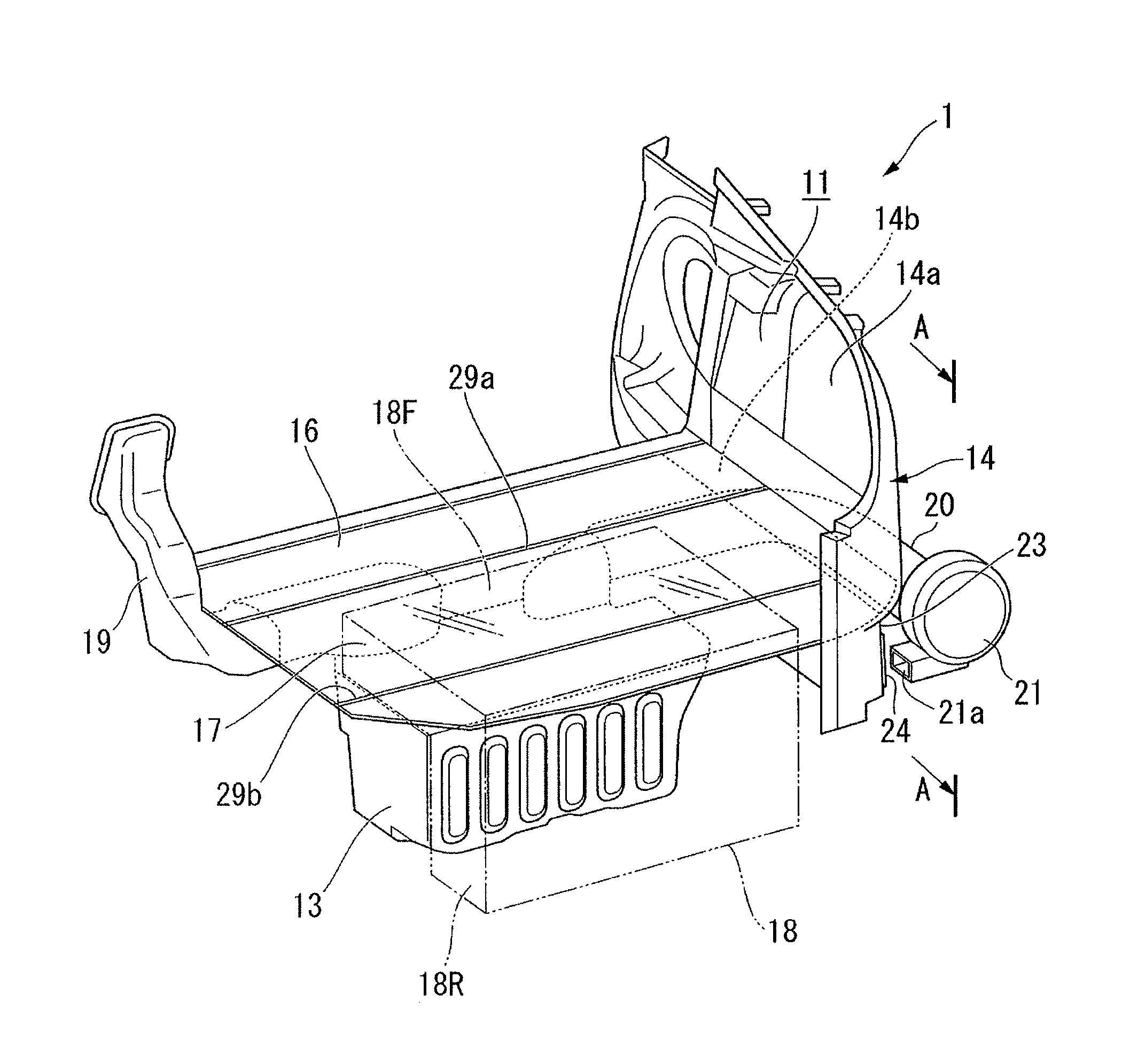
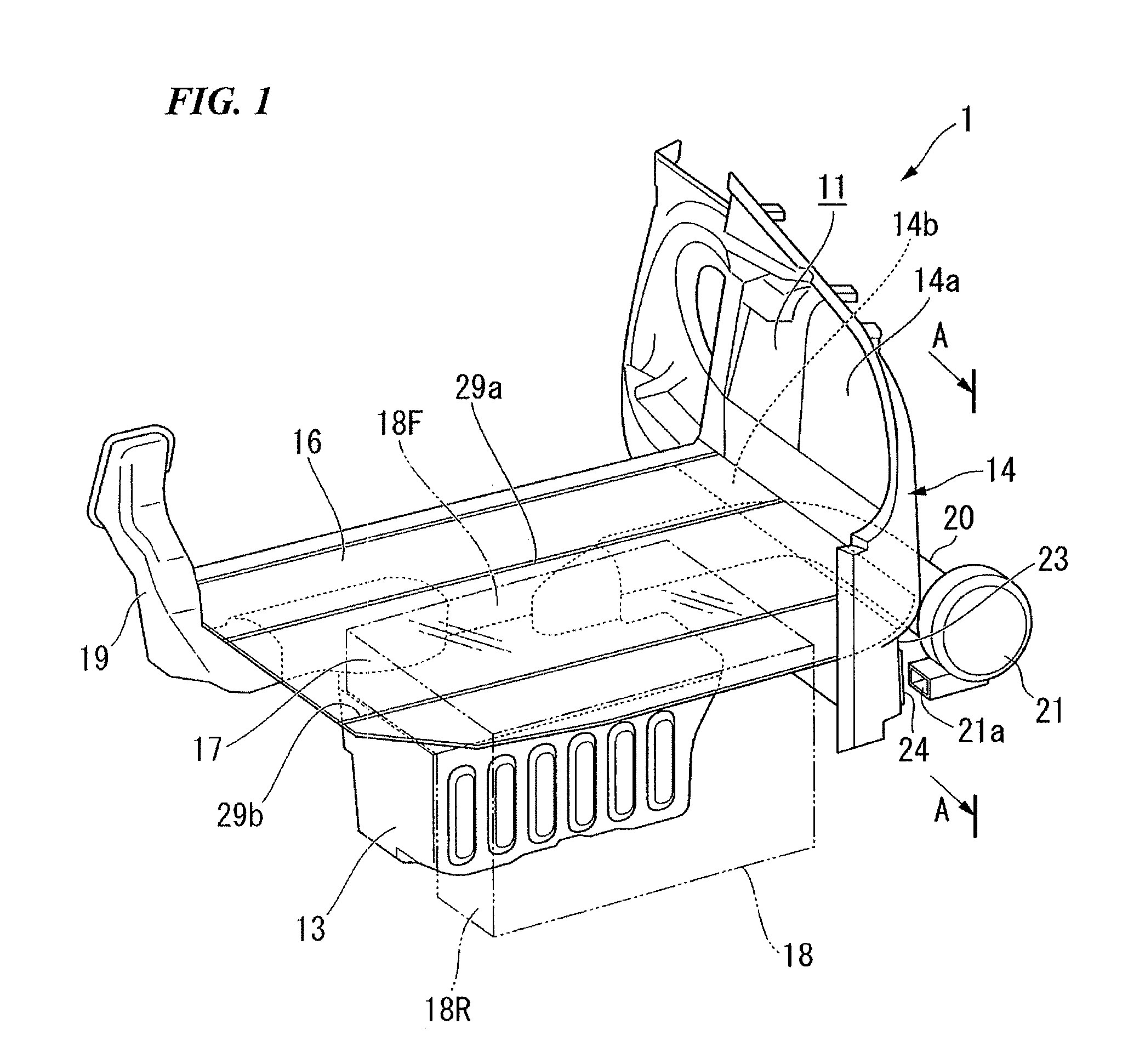
[0020]As described above, FIG. 1 is a generalized perspective view of a rear portion of a vehicle I seen from an upper diagonal side of a backside of the vehicle 1 equipped with the battery cooling structure according to the present invention. FIG. 2 is a plane view of a model of the rear portion of the vehicle 1. FIG. 3 is a cross sectional view of FIG. 1 showing the vehicle 1, corresponding to an A-A cross section. In order to facilitate the description of the internal structure, some of the parts placed near the viewpoint of FIG. 1 are omitted from FIG. 1.

[0021]The vehicle 1 according to the present embodiment includes a luggage compartment 11 in a back side of a rear seat 10 (refer to FIG. 2). The luggage compartment 11 is connected with an interior of the vehicle 1. As shown in FIG. 1, a battery box 13 is placed in a lower part of a fron...


PUM


Abstract

A battery cooling structure which cools a battery equipped on a vehicle, the battery cooling structure including: a fan sending an air to cool the battery; and a sound insulation wall including a sound insulation material which insulates noise wherein the sound insulation wall faces an exhaust outlet of the fan.

Description

BACKGROUND OF THE INVENTION[0001]The present application claims priority on Japanese Patent Application No. 2008-233109, filed Sep. 11, 2008, the content of which is incorporated herein by reference.FIELD OF THE INVENTION[0002]The present invention relates to a battery cooling structure. The cooling structure cools a battery equipped in a vehicle by sending air to the battery.DESCRIPTION OF THE RELATED ART[0003]High voltage batteries are equipped on battery vehicles, hybrid vehicles, and the like, in order to supply energy to the vehicle. Such high voltage batteries emit a large amount of heat. Therefore, increases in temperature have been restrained by using a fan that sends air (refer to, for example, Japanese Unexamined Patent Application, First Publication No. 2004-42698 (hereinafter referred to as “Patent Document 1”)).[0004]According to the battery cooling structure disclosed in Patent Document 1, a battery box is placed on the back side of a rear seat. A suction duct and a di...

Claims


Application Information

Patent Timeline
IPC IPC(8): F28D15/00F28F13/00B60K11/06B60R13/08H01M50/202H01M50/244H01M50/249
CPCB60K1/04B60K2001/005H01M2/1083H01M10/5073H01M10/5016H01M10/5057H01M10/5067H01M10/5004H01M10/625H01M10/6563H01M10/6556H01M10/6566H01M10/613Y02E60/10H01M50/249H01M50/202H01M50/244
Inventor NAKAMURA, MITSUYOSHI
Owner HONDA MOTOR CO LTD
Why Eureka
Try Eureka