Computer peripheral with removable active element cartridge

a technology of active elements and peripherals, applied in computing, instruments, electric digital data processing, etc., can solve the problems of rigidly-set configuration production efficiency, inability to easily sub-assemble pedals, and existing non-cartridge foot pedals

Active Publication Date: 2012-10-23
KINESIS CORP
View PDF30 Cites 11 Cited by
  • Summary
  • Abstract
  • Description
  • Claims
  • Application Information

AI Technical Summary

Problems solved by technology

The drawbacks of existing non-cartridge foot pedals relate in part to the production inefficiencies of rigidly-set configurations.
Pedals cannot be easily assembled as a general purpose subassembly and then configured for different uses and markets as needed.
Users also experience drawbacks with the existing non-cartridge foot pedal due to the difficulty in carrying out repairs or changes in the field.
It is impossible to accurately predict inventory requirements for each type and inefficient to order all these different versions to be configured by suppliers.
It is both difficult and time consuming to disassemble and reconfigure a conventional pedal for a different configuration.
Pedals normally must be designed to hold up under the force and impact of many foot actions, so they are not primarily designed for easy disassembly.
In fact, this strength requirement makes foot pedals inherently difficult to take apart.
Also this requirement to resist many impacts has led historically to bulky, high-profile designs.
Stronger modern materials and manufacturing processes allow low-profile designs which may be functionally and aesthetically preferred by users, but such pedals may nonetheless twist if pressed on an edge or corner, and thus fail to trigger properly, preventing the evolution of desirable modern designs.
Furthermore, some conventional pedals have mechanisms to adjust travel distance, which would simultaneously, and often undesirably, change biasing force.
If it were desired to change biasing force in a conventional pedal, simply changing the spring, for example, would be difficult because of the difficulty of disassembly.
If biasing force were made adjustable, it has not been possible to change force independent of travel distance with a compact, self-contained device.
Additionally, conventional pedals are noisy to operate, which is not desirable in some operational environments such as an office or medical setting.
In addition, conventional peripheral triggering devices such as foot pedals and foot and / or hand mouse generated triggering noises on both down and upstrokes that are distracting and can cause wearing of components.
Furthermore, conventional devices that have attempted triggering in regions spaced from the location of internal switches that detect triggering, such as in corners of a pedal or mouse trigger, typically result in inadequate activation of the switches.

Method used


Image

  • Computer peripheral with removable active element cartridge
  • Computer peripheral with removable active element cartridge
  • Computer peripheral with removable active element cartridge

Examples


Embodiment Construction

[0040]The present disclosure relates to a novel peripheral device, in one aspect, including an improved foot pedal or foot switch for use with electronic devices which can be configured to perform virtually silently, with adjustable force which does not affect pedal travel, and in which the active elements can be housed in a removable cartridge.

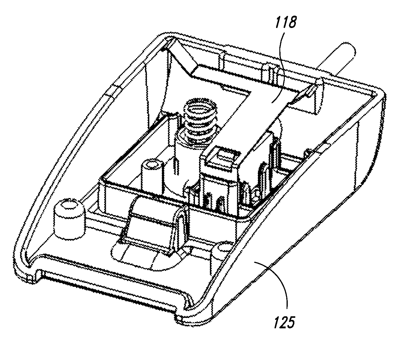
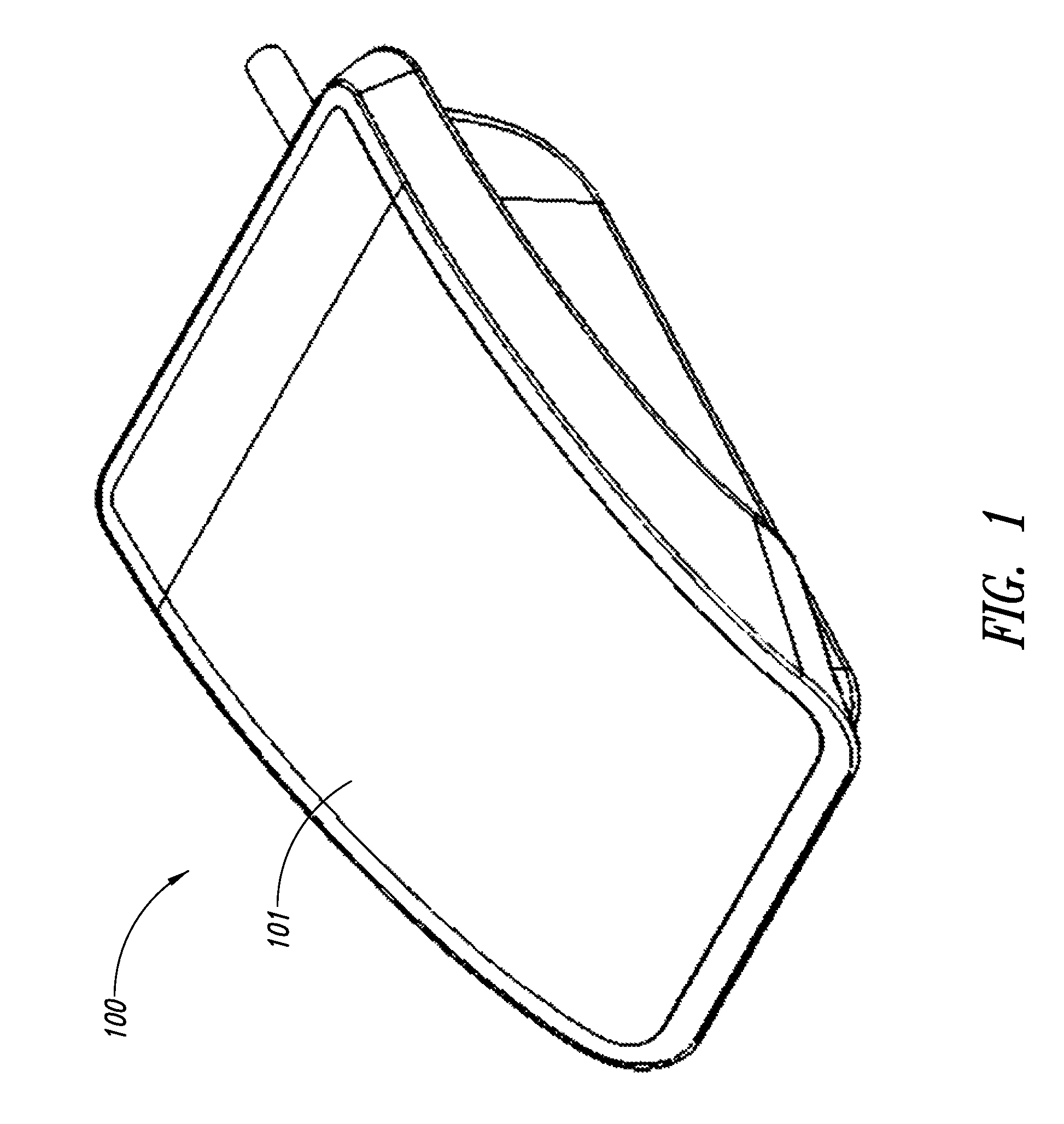
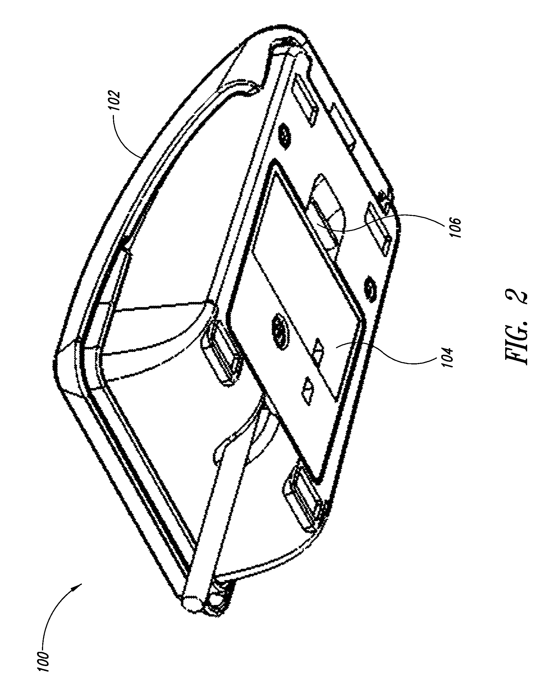
[0041]FIG. 1 illustrates one embodiment of a peripheral device 100 having an upper member 101, all or a portion of which can form one or more triggering interfaces of the peripheral device 100. As illustrated in FIG. 2, the peripheral device 100 includes a body 102 and a cartridge 104 removably coupled to the body 102. The cartridge 104 and / or the body 102 may include a release or detent mechanism or feature 106 that allows easy manual removal of the cartridge 104 without requiring tools. FIG. 3 illustrates the peripheral device 100 with the upper member 101 removed to show an interior of the device according to one aspect. The cartridge 104 ...


PUM


Abstract

A peripheral device includes at least one active or trigger element housed in a cartridge that is removably mounted. A user can easily remove the cartridge with the active or trigger elements without using special tools. In some embodiments, the peripheral device can include a leveling member between a detection switch and a triggering interface to facilitate effective actuation of the triggering interface and activation of the detection switch from regions spaced from the detection switch. Some embodiments can include silencing or dampening features or structures to minimize or substantially eliminate sound generated upon activation of the triggering interface.

Description

BACKGROUND[0001]1. Technical Field[0002]The present disclosure generally relates to peripherals for electronic devices, and more particularly, to a computer peripheral, more specifically an input device such as a foot pedal and / or foot and / or hand mouse, with active elements and / or structural features which are removable and / or adjustable.[0003]2. Description of the Related Art[0004]The drawbacks of existing non-cartridge foot pedals relate in part to the production inefficiencies of rigidly-set configurations. Pedals cannot be easily assembled as a general purpose subassembly and then configured for different uses and markets as needed. Users also experience drawbacks with the existing non-cartridge foot pedal due to the difficulty in carrying out repairs or changes in the field. For example, one conventional foot pedal family includes models using three different types of cables (short 2-pin connector, long mini-phono connector, long RJ11 connector) and two different types of swit...

Claims


Application Information

Patent Timeline
Patent Type & Authority Patents(United States)
IPC IPC(8): G09G5/08
CPCG06F3/0334G06F3/03543G06F3/039
Inventor HARGREAVES, WILLIAM RUDOLPHBUUS, CARSTENANDO, MARK SHINTARO
Owner KINESIS CORP
Why Eureka
Try Eureka