Gas turbine exhaust sound suppressor and associated methods

a technology of exhaust noise suppression and gas turbine, which is applied in the field of exhaust silencers or noise suppression in gas turbines, can solve the problems of combustion noise, fan noise, turbulent noise, and combustion noise in the exhaust of gas turbine engines, and achieve the effect of reducing low frequency exhaust flow nois

Inactive Publication Date: 2010-05-18
SIEMENS ENERGY INC
View PDF37 Cites 11 Cited by
  • Summary
  • Abstract
  • Description
  • Claims
  • Application Information

AI Technical Summary

Benefits of technology

[0011]In view of the foregoing background, it is therefore an object of the present invention to provide an exhaust sound suppressor and method for a gas turbine that reduces low frequency exhaust flow noise while avoiding the creation of additional acoustical standing waves, e.g. from wake shedding at certain predictable frequencies or from standing acoustical waves at certain predictable frequencies referred to as duct modes.
[0015]A method aspect is directed to suppressing sound in an exhaust flow from a gas turbine having an exhaust duct defining an exhaust passage and a flow direction. The method may include providing a plurality of elongated flow obstruction members, e.g. pipes or airfoils, at least some of which have different widths, and positioning each of the elongated flow obstruction members within the exhaust passage at a respective angle within a predetermined angular range transverse to the flow direction to reduce acoustic waves within the exhaust flow. The predetermined angular range may be greater than or equal to 10 degrees from normal to the flow direction.

Problems solved by technology

The gas flow through the engine generates acoustic energy or noise.
The main sources of noise in a gas turbine engine exhaust are combustion noise, turbulent noise, and fan noise.
Combustion noise originates within the combustion chamber of the gas turbine.
Turbulent noise includes all the dynamic instabilities resulting from the high velocity exhaust stream such as the jet noise resulting from the localized flow separation at boundary discontinuities, or periodic high velocity flow impact on exhaust duct structural boundaries.
Fan noise results from the periodic passage of the individual turbine blades which creates pressure pulsations that propagate downstream in the exhaust duct in the same way that inlet fan noise is generated and propagates out the gas turbine inlet.
However, these approaches may introduce flow effects, e.g. wake shedding, that cause additional acoustical standing waves where none had existed before.

Method used


Image

  • Gas turbine exhaust sound suppressor and associated methods
  • Gas turbine exhaust sound suppressor and associated methods
  • Gas turbine exhaust sound suppressor and associated methods

Examples


Embodiment Construction

[0024]The present invention will now be described more fully hereinafter with reference to the accompanying drawings, in which preferred embodiments of the invention are shown. This invention may, however, be embodied in many different forms and should not be construed as limited to the embodiments set forth herein. Rather, these embodiments are provided so that this disclosure will be thorough and complete, and will fully convey the scope of the invention to those skilled in the art. Like numbers refer to like elements throughout, and prime notation is used to indicate similar elements in alternative embodiments. The dimensions of layers and regions may be exaggerated in the figures for clarity.

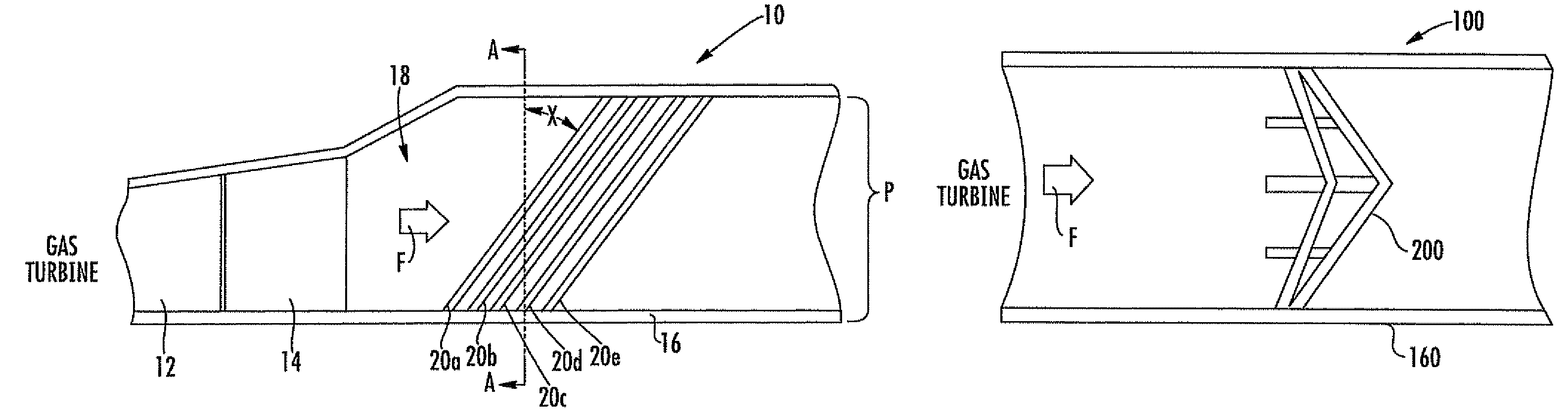
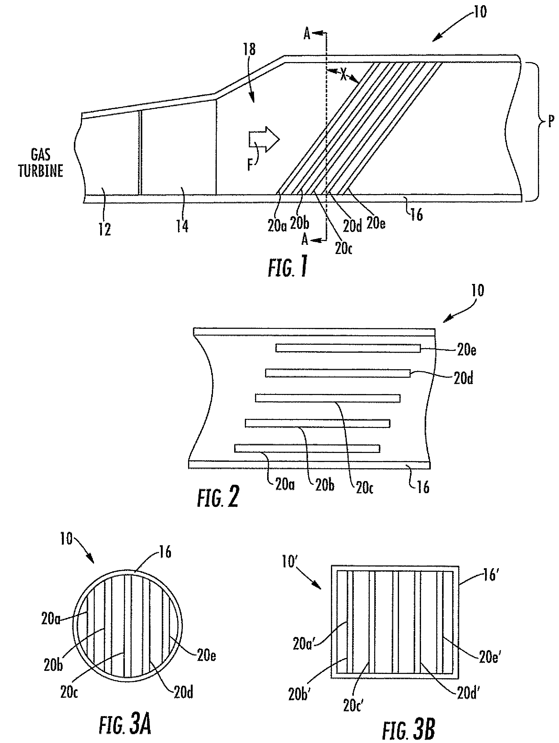
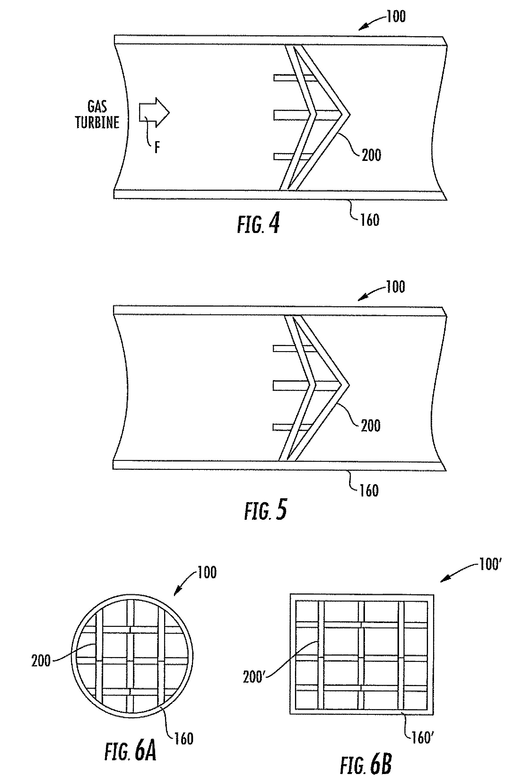
[0025]As discussed above, the turbulent high energy exhaust flow from a gas turbine contains and may generate high levels of low frequency sound, e.g. less than 100 Hz. Some proportion of such low frequency sound is contained in the exhaust flow at the gas turbine exit and some is generated ...


PUM


Abstract

The gas turbine exhaust sound suppressor, or exhaust silencer, and method are for a gas turbine and reduce low frequency exhaust flow noise while avoiding the creation of additional acoustical standing waves, e.g. from wake shedding at certain predictable frequencies. A plurality of elongated flow obstruction members, e.g. pipes or airfoils, extend within the exhaust passage to reduce acoustic waves within the exhaust flow, and at least some of the elongated flow obstruction members have different widths. Each of the elongated flow obstruction members is positioned at a respective angle within a predetermined angular range transverse to the flow direction, with the predetermined angular range being greater than or equal to 10 degrees from normal to the flow direction.

Description

FIELD OF THE INVENTION[0001]The present invention relates to the field of gas turbines, and, more particularly, to exhaust silencers or noise suppression in gas turbines and related methods.BACKGROUND OF THE INVENTION[0002]A gas turbine engine includes a compression section, a combustion section, and a turbine section. A flow path for the gases extends axially through the engine. The compression section has a rotor assembly that includes an array of rotor blades that are angled with respect to the approaching gas flow. The compression section also has a stator assembly that includes an array of stator vanes. Duct walls extend circumferentially with respect to the flow path to form the boundaries for the working medium gases in the fan section.[0003]As the rotor assembly rotates, the blades increase the pressure of the gases. The rotor blades also increase the velocity of the gases and direct the flow of gases from the engine axial direction to the blade rotation direction. The gases...

Claims


Application Information

Patent Timeline
Patent Type & Authority Patents(United States)
IPC IPC(8): B64F1/26F01N1/08F01N1/00F02K1/00
CPCF02K1/827
Inventor PUTNAM, ROBERT A.
Owner SIEMENS ENERGY INC
Why Eureka
Try Eureka