Fan with sound-muffling box

a technology of fan and sound, applied in the direction of machines/engines, mechanical equipment, liquid fuel engines, etc., can solve the problems of low static pressure, high level of airflow collision noise, low input of conventional fans, etc., and achieve low input, high static pressure, and low pressure loss

Inactive Publication Date: 2010-03-25
PANASONIC CORP
View PDF1 Cites 10 Cited by
  • Summary
  • Abstract
  • Description
  • Claims
  • Application Information

AI Technical Summary

Benefits of technology

[0018]The present invention provides a fan with a sound deadening box, the fan having a unique shape and arrangement of the sound deadening member, thereby having a low pressure loss in a sound-deadening air passage, a low input, high static pressure, and a low level of airflow collision noise.
[0019]Furthermore, the present invention provides a fan with a sound deadening box, the fan having a low occurrence of turbulent flow, thereby having a low pressure loss, high air flow, a low input, and a low level of turbulent flow noise.
[0020]A fan with a sound deadening box of the present invention includes a box-shaped body, a double inlet centrifugal fan, an inlet-port sound absorber, casing-inlet-port-side air passages, and a first inlet-port-sound-absorber air passage. The body includes a body air inlet and a body air outlet facing each other. The double inlet centrifugal fan includes a discharge port, a spiral scroll, casing inlet ports, a fan casing having casing side plates on both sides thereof, the casing side plates having the casing inlet ports, a motor disposed on a side of one of the casing inlet ports, and a double inlet impeller driven by the motor. The inlet-port sound absorber is disposed between the body air inlet and the double inlet centrifugal fan. The casing-inlet-port-side air passages are formed in spaces between the body air inlet and the casing inlet ports, the spaces being sandwiched between the double inlet centrifugal fan and the inner surfaces of the body that face the casing inlet ports. The first inlet-port-sound-absorber air passage is formed to have a triangular prism shape by cutting a corner of a ridge line of the inlet-port sound absorber. With this structure, the fan with the sound deadening box has a low pressure loss and a low level of airflow collision noise, while ensuring the air flow.
[0021]Moreover, a fan with a sound deadening box of the present invention includes a box-shaped body, a double inlet centrifugal fan, an inlet-port sound absorber, casing-inlet-port-side air passages, and a second inlet-port-sound-absorber air passage. The body includes a body air inlet and a body air outlet facing each other. The double inlet centrifugal fan includes a discharge port, a spiral scroll, casing inlet ports, a fan casing having casing side plates on both sides thereof, the casing side plates having the casing inlet ports, a motor disposed on a side of one of the casing inlet ports, and a double inlet impeller driven by the motor. The inlet-port sound absorber is disposed between the body air inlet and the double inlet centrifugal fan. The casing-inlet-port-side air passages are formed in spaces between the body air inlet and the casing inlet ports, the spaces being sandwiched between the double inlet centrifugal fan and the inner surfaces of the body that face the casing inlet ports. The second inlet-port-sound-absorber air passage is formed to have a rectangular prism shape in a space between the surface of the inlet-port sound absorber that does not face the casing-inlet-port-side air passages and the inner surface of the body that faces the inlet-port sound absorber. With this structure, the fan with the sound deadening box has a low pressure loss and a low level of airflow collision noise, while ensuring the air flow.
[0022]Furthermore, a fan with a sound deadening box of the present invention includes a box-shaped body, a double inlet centrifugal fan, casing-inlet-port-side air passages, a body sound absorber, and a rectifying member. The body includes a body air inlet and a body air outlet facing each other. The double inlet centrifugal fan includes a discharge port, a spiral scroll, casing inlet ports, a fan casing having casing side plates on both side thereof, the casing side plates having the casing inlet ports, a motor disposed on a side of one of the casing inlet ports, and a double inlet impeller driven by the motor. The casing-inlet-port-side air passages are formed in spaces between the body air inlet and the casing inlet ports, the spaces being sandwiched between the double inlet centrifugal fan and the inner surfaces of the body that face the casing inlet ports. The body sound absorber is formed between the casing inlet port and the inner surface of the body. The rectifying member is formed on the body sound absorber and has a vertical rectification stage and a horizontal rectification stage. The rectifying member has a height smaller than the height inside the body, and is disposed to face the casing side plate in parallel therewith in the vicinity of the tongue of the casing side plate. Thus, the rectifying member narrows the casing-inlet-port-side air passage both toward the discharge port and from a body plane side on the tongue side of the double inlet centrifugal fan. The vertical rectification stage is located in front of the casing inlet port, and orthogonal to an airflow passing through the casing-inlet-port-side air passage. The horizontal rectification stage is located in parallel with the airflow passing through the casing-inlet-port-side air passage. With this structure, the fan with the sound deadening box has a low pressure loss due to a low turbulent flow in the vicinity of the casing inlet port, high air flow, a low input, and a low level of turbulent flow noise.
[0023]Furthermore, a fan with a sound deadening box of the present invention includes a box-shaped body, a double inlet centrifugal fan, casing-inlet-port-side air passages, a body sound absorber, and a guide member. The body includes a body air inlet and a body air inlet facing each other. The double inlet centrifugal fan includes a discharge port, a spiral scroll, casing inlet ports, a fan casing having casing side plates on both sides thereof, the casing side plates having the casing inlet ports, a motor disposed on a side of one of the casing inlet ports, and a double inlet impeller driven by the motor. The casing-inlet-port-side air passages are formed in spaces between the body air inlet and the casing inlet ports, the spaces being sandwiched between the double inlet centrifugal fan and the inner surfaces of the body that face the casing inlet ports. The body sound absorber is formed between the casing inlet port and the inner surface of the body. The guide member is formed on the body sound absorber and has vertical guide stage. The guide member has substantially the same height as the height inside the body and is disposed to face the casing side plate in parallel therewith. Thus, the guide member narrows the casing-inlet-port-side air passage toward the discharge port. The vertical guide stage is located in front of the casing inlet port, and orthogonal to an airflow passing through the casing-inlet-port-side air passage. With this structure, the fan with the sound deadening box has a low pressure loss due to a low turbulent flow in the vicinity of the casing inlet port, high air flow, a low input, and a low level of turbulent flow noise.

Problems solved by technology

As a result, conventional fan 100 has a high input, low static pressure, and a high level of airflow collision noise due to a narrow passage.
The pre-swirling flow also collides with the airflow from air passage 113a, thereby causing turbulent flow in the vicinity of port 109a. As a result, fan 100a has low air flow due to pressure loss, a high input, and a high level of turbulent flow noise.

Method used


Image

  • Fan with sound-muffling box
  • Fan with sound-muffling box
  • Fan with sound-muffling box

Examples


first embodiment

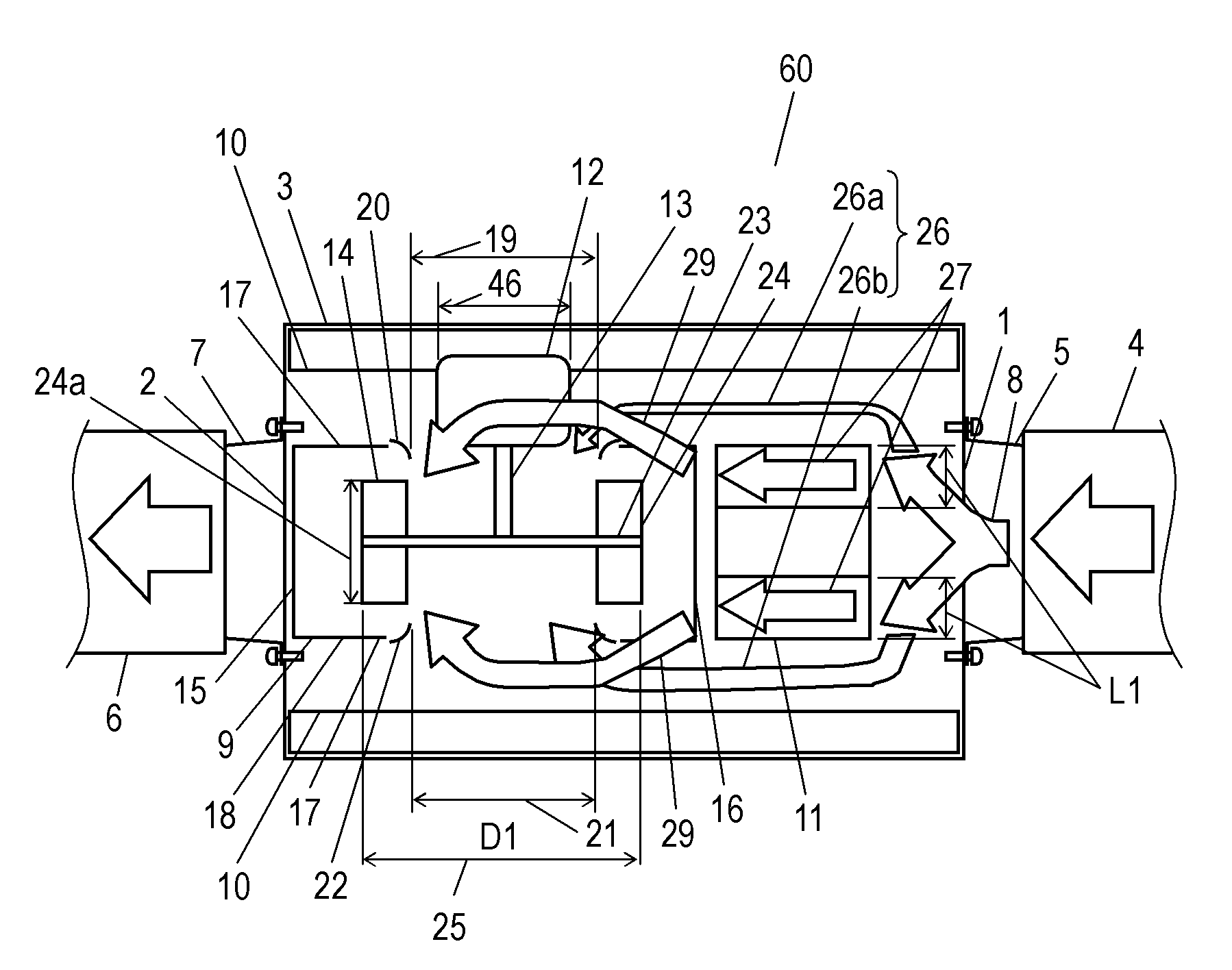
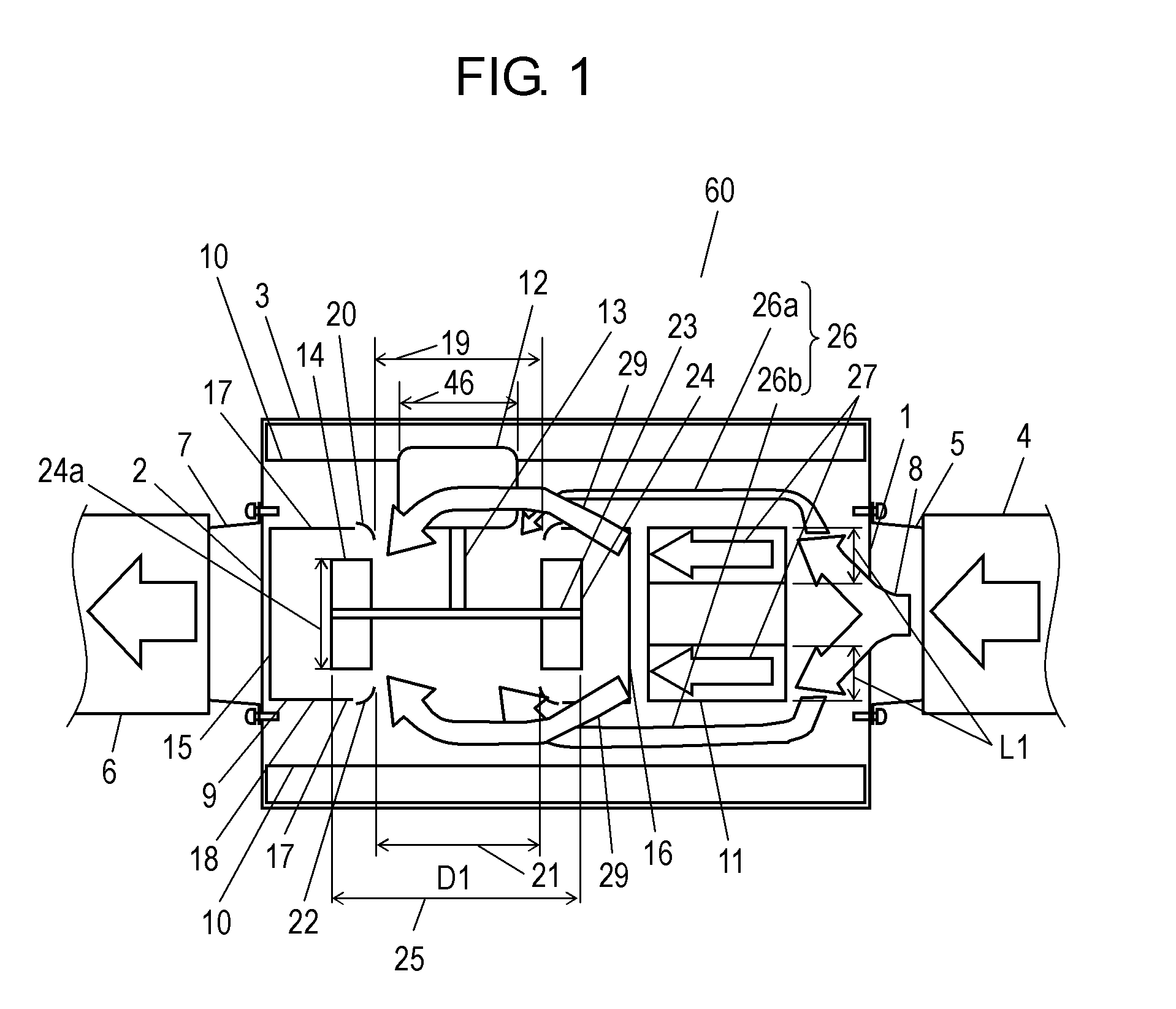
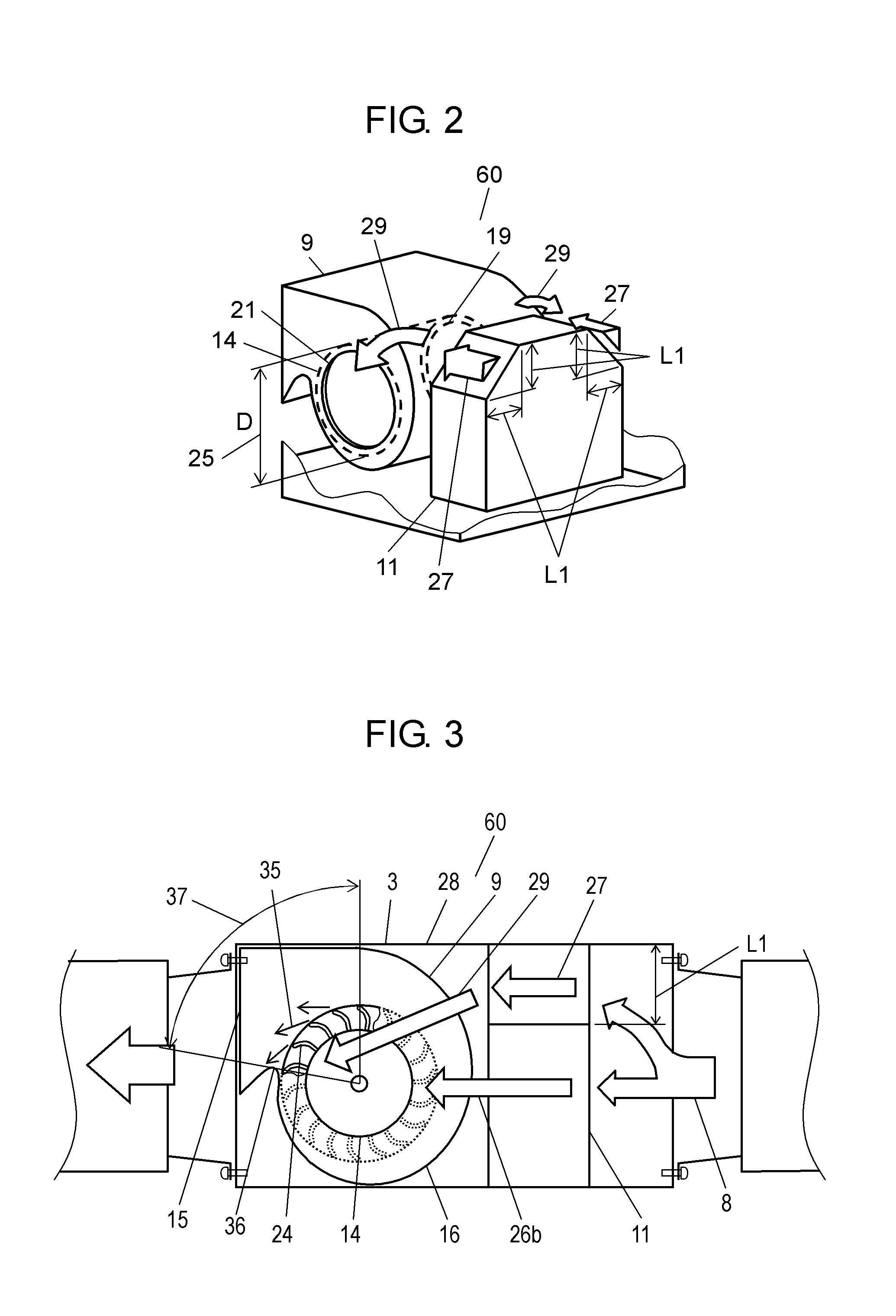
[0118]A first embodiment of the present invention will be described as follows with reference to FIGS. 1 to 5. FIG. 1 is a plan view of fan 60 with a sound deadening box (hereinafter, fan 60) according to the first embodiment. FIG. 2 is a perspective view of fan 60 of FIG. 1 in the vicinity of inlet-port sound absorber 11 (hereinafter, sound absorber 11). FIG. 3 is a side view of fan 60 of FIG. 1. FIG. 4 is a side view where fan 60 of FIG. 1 is installed. FIG. 5 is a non-dimensional characteristic diagram showing characteristics of fan 60 of FIG. 1.

[0119]As shown in FIGS. 1 to 4, fan 60 includes box-shaped body 3. Body 3 is provided on its opposite sides with body air inlet 1 (hereinafter, inlet 1) and body air outlet 2 (hereinafter, outlet 2). Inlet 1 is disposed on the suction side of body 3 and connected to suction-side duct 4 (hereinafter, duct 4) so as to draw the air indoors 31 into body 3. Outlet 2 is disposed on the exhaust side of body 3 and connected to exhaust-side duct 6...

second embodiment

[0131]A second embodiment of the present invention will be described as follows with reference to drawings. The same components as in the first embodiment are denoted by the same reference numerals, and thus a detailed description thereof will be omitted. FIG. 6 is a plan view of fan 60a with a sound deadening box (hereinafter, fan 60a) according to the second embodiment. FIG. 7A is a perspective view of fan 60a of FIG. 6 in the vicinity of inlet-port sound absorber 11. FIG. 7B is a perspective view of another fan 60b with the sound deadening box (hereinafter, fan 60b) according to the second embodiment in the vicinity of inlet-port sound absorber 11. FIG. 8 is a side view of fan 60a of FIG. 6. FIG. 9 is a non-dimensional characteristic diagram showing characteristics of fans 60a and 60b.

[0132]Fan 60a of the second embodiment includes second inlet-port-sound-absorber air passage 38 (hereinafter, air passage 38) instead of first inlet-port-sound-absorber air passages 27 of fan 60 of...

third embodiment

[0142]A third embodiment of the present invention will be described as follows with reference to drawing. The same components as in the first and second embodiments are denoted by the same reference numerals, and thus a detailed description thereof will be omitted. FIG. 10 is a plan view of fan 60c with a sound deadening box (hereinafter, fan 60c) according to the third embodiment. FIG. 11A is a perspective view of fan 60c of FIG. 10 in the vicinity of inlet-port sound absorber 11. FIG. 11B is a perspective view of another example of fan 60c with the sound deadening box according to the third embodiment in the vicinity of inlet-port sound absorber 11.

[0143]Fan 60c of the third embodiment includes scroll rear-side air passage 43 (hereinafter, air passage 43) in addition to the components of fan 60 of the first embodiment. More specifically, as shown in FIGS. 10 and 11A, sound absorber 11 and scroll 16 are spaced from each other at a dimension L3 where air passage 43 is formed. Air pa...


PUM


Abstract

A fan (60) with a sound deadening box has in its body (3) a double inlet centrifugal fan (9) and an inlet-port sound absorber (11) formed between the fan (9) and a body air inlet (1). The fan (60) further includes a casing-inlet-port-side air passage (26) and triangular prism shaped first inlet-port-sound-absorber air passage (27). With this structure, the fan (60) has a low pressure loss, a low input, high static pressure, and a low level of airflow collision noise.

Description

TECHNICAL FIELD[0001]The present invention relates to a fan with a sound deadening box having a sound deadening member, the fan being installed in an air passage of a ventilation fan or the like.BACKGROUND ART[0002]Some conventional fans with sound deadening boxes include a flow-dividing sound deadening member in the vicinity of their body air inlets. The flow-dividing sound deadening member means a sound deadening member having a corner with a recess on the opposite-motor-side casing-inlet-port-side air passage thereof. One such conventional fan is disclosed in Patent Document 1.[0003]Other conventional fans with sound deadening boxes include an air guide plate in the vicinity of their casing inlet ports. One such conventional fan is disclosed in Patent Document 2.[0004]One of the first-mentioned conventional fans with sound deadening boxes including a flow-dividing sound deadening member in the vicinity of their body air inlets will be described as follows with reference to drawin...

Claims


Application Information

Patent Timeline
Patent Type & Authority Applications(United States)
IPC IPC(8): F04D29/66H02K5/24
CPCF04D29/66
Inventor SINZAKI, KOUJI
Owner PANASONIC CORP
Why Eureka
Try Eureka