Method for mixing fluid streams

a technology of fluid streams and mixing methods, applied in the direction of mixing, mechanical equipment, transportation and packaging, etc., can solve the problems of increasing the distance in a duct to achieve the same degree of mixing, increasing the distance in a duct, and increasing the degree of mixing or mixing efficiency. , to achieve the effect of improving the degree of mixing or mixing efficiency

Active Publication Date: 2008-11-11
UMICORE AG & CO KG
View PDF29 Cites 24 Cited by
  • Summary
  • Abstract
  • Description
  • Claims
  • Application Information

AI Technical Summary

Benefits of technology

[0013]EP 1,170,054 B1 discloses a mixer for mixing gases and other Newtonian liquids comprising built-in-surfaces positioned within a flow channel so as to influence the flow. The built-in-surfaces are positioned transverse to the main flow direction and partly overlap. This provides the homogenisation of the velocity profile of the flow by means of the built-in-surfaces. It is stated that the built-in-surfaces can be round discs, disks with delta-shaped or triangular basic shapes, or elliptical or parabola-shaped disks. The mixer enables fast mixing of the stream in the flow channel within a very short mixing distance.
[0040]As a result of the invention the degree of mixing or mixing efficiency is improved within a given mixing distance or within a given (commercially acceptable) pressure loss range. This improvement in mixing with respect to for example circular mixing devices can be quantified (see later in connection with example given in FIG. 3). The benefits of the invention can also be seen in terms of pressure loss: it is now possible to operate with lower pressure loss than is normally possible when operating with conventional circular mixing devices. Alternatively, the mixing distance in a duct needed to obtain the same degree of mixing compared with the use of circular mixers is reduced. The mixing distance in the duct can be reduced (in dimensionless terms) significantly with respect to when utilising a conventional circular mixer. For instance, for an arrangement comprising a single mixing device within a square duct, the mixing distance necessary to achieve a given degree of mixing can be reduced from three hydraulic diameters, when utilising a circular mixing device, to two hydraulic diameters, when utilising the inventive mixing device.

Problems solved by technology

The use of static mixers has the penalty that their use manifests itself in considerable pressure loss in the duct, with the attendant effect of costly energy losses.
Because the outlet opening of the second stream being injected into the duct carrying the first major stream may only protrude a short distance inwardly from the wall of the duct, the concentration of the active species of the second stream, e.g ammonia, towards the centre of the duct may tend to decrease, thus contributing to poor mixing.
Poor mixing or poor homogeneity of the injected ammonia may imply higher NOx levels in the stack as well as unwanted levels of ammonia passing unreacted through the catalyst unit.
These describe relatively expensive hollow mixing devices with protrusions or projections directed inward from the periphery of the devices.
However, they are rather expensive and may require a greater number of injection points for the introduction of a second stream into the major fluid stream than when utilising regular shaped static mixing devices.
This configuration promotes the creation of turbulent flow regions on the back side of the mixing device, but imposes a great pressure loss.
The projected area of the mixer on a plane transverse to the main stream direction is zero; consequently, no turbulent flow regions are created and poor mixing results.
However, the pressure loss is very low.
A major problem confronted in the art is therefore that it is desirable to obtain a good mixing of interacting fluid streams within a relatively short mixing distance along the duct without compromising the energy efficiency of the system imposed by the high pressure loss exerted by the mixing device.
Another problem encountered with particularly conventional regular shaped mixing devices, for instance circular or elliptical mixers, is that the positioning of these within rectangular or square ducts may result in relative poor mixing at or near the corner regions of the duct.
The inventive mixing devices incorporate a certain degree of voids or empty spaces in between protrusions at their periphery that result in a relatively low resistance to the major fluid stream, hence further reducing pressure losses.

Method used


Image

  • Method for mixing fluid streams
  • Method for mixing fluid streams
  • Method for mixing fluid streams

Examples


Embodiment Construction

[0048]The invention is illustrated in the accompanying drawings, wherein

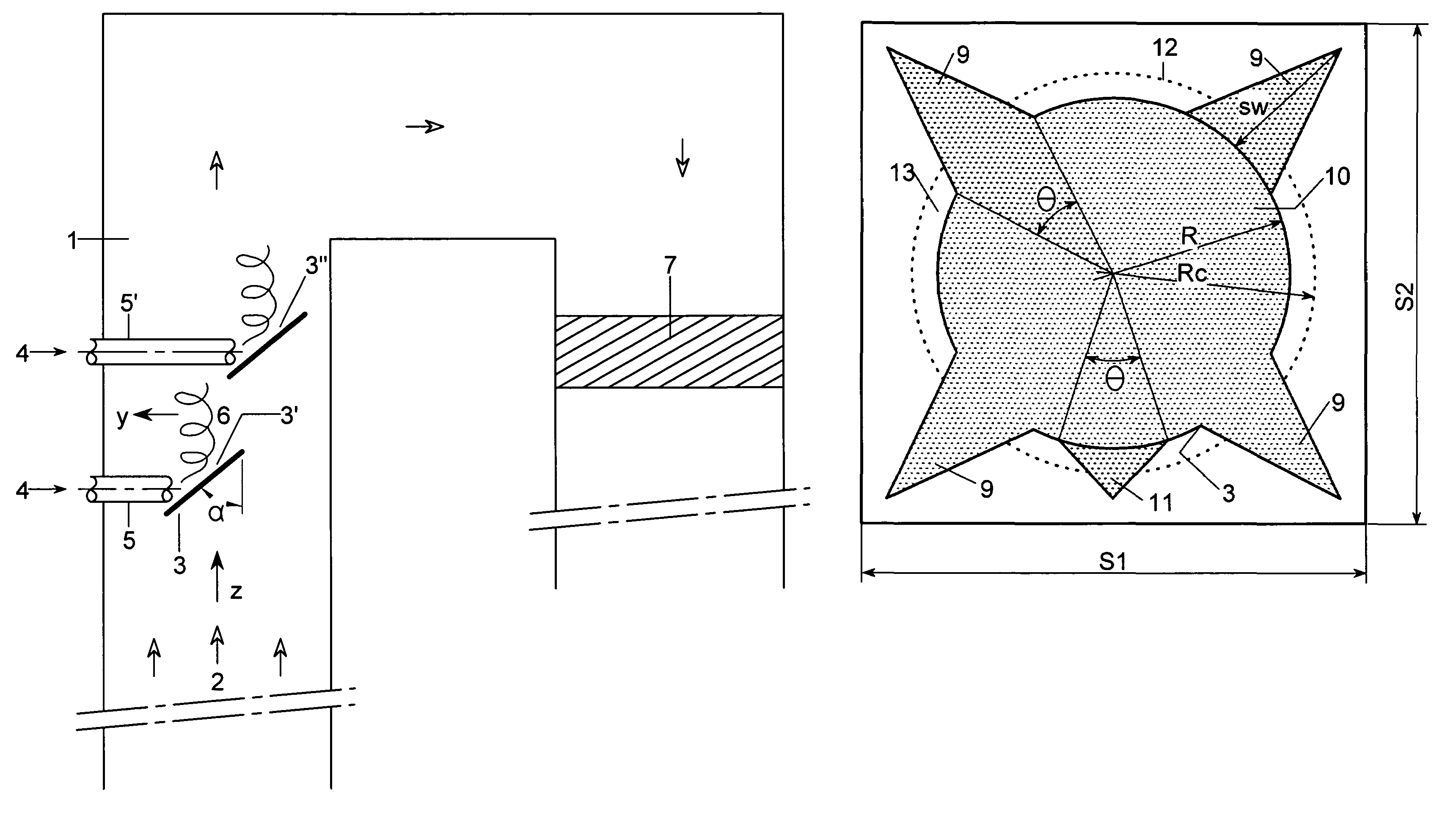
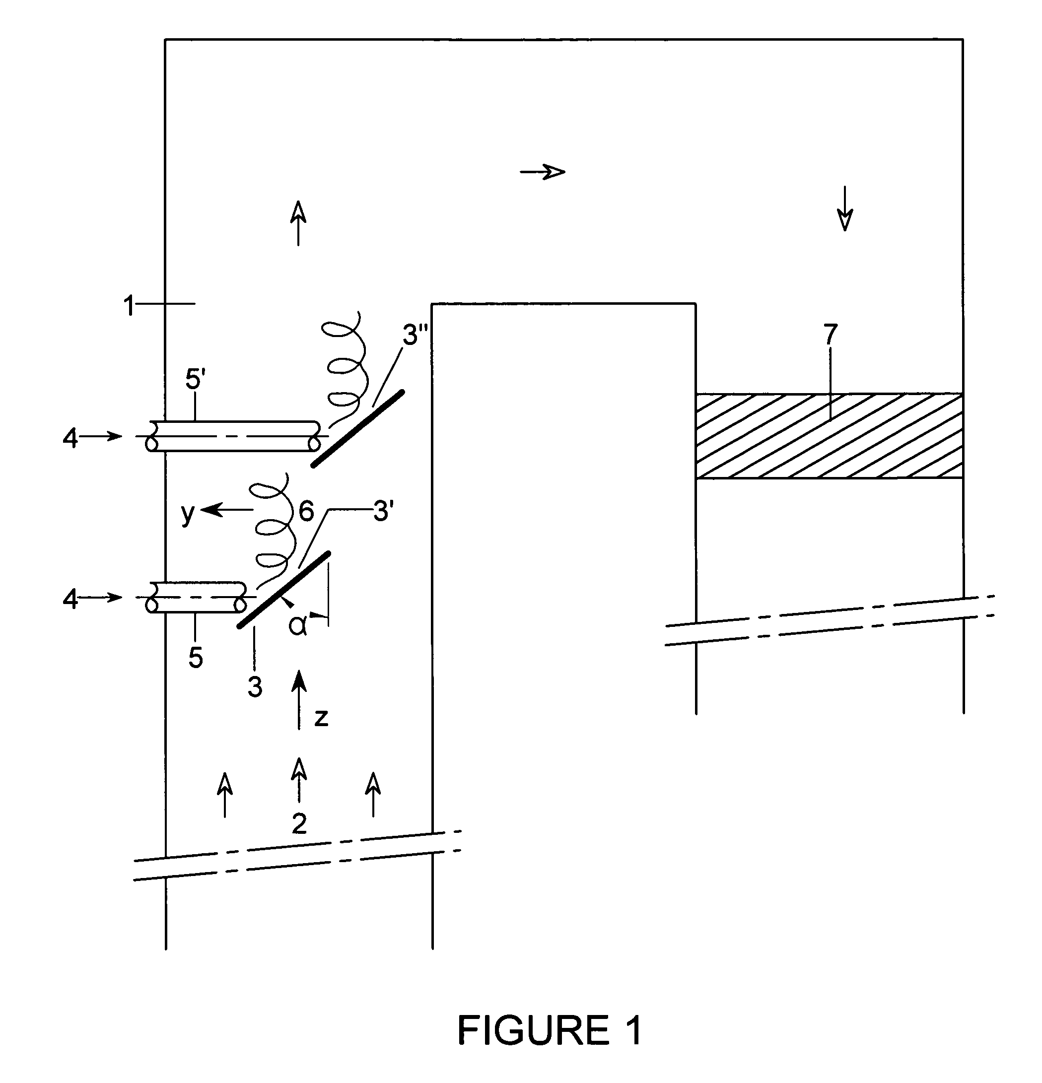
[0049]FIG. 1 shows a schematic vertical cross-sectional view of a flue gas section according to the invention.

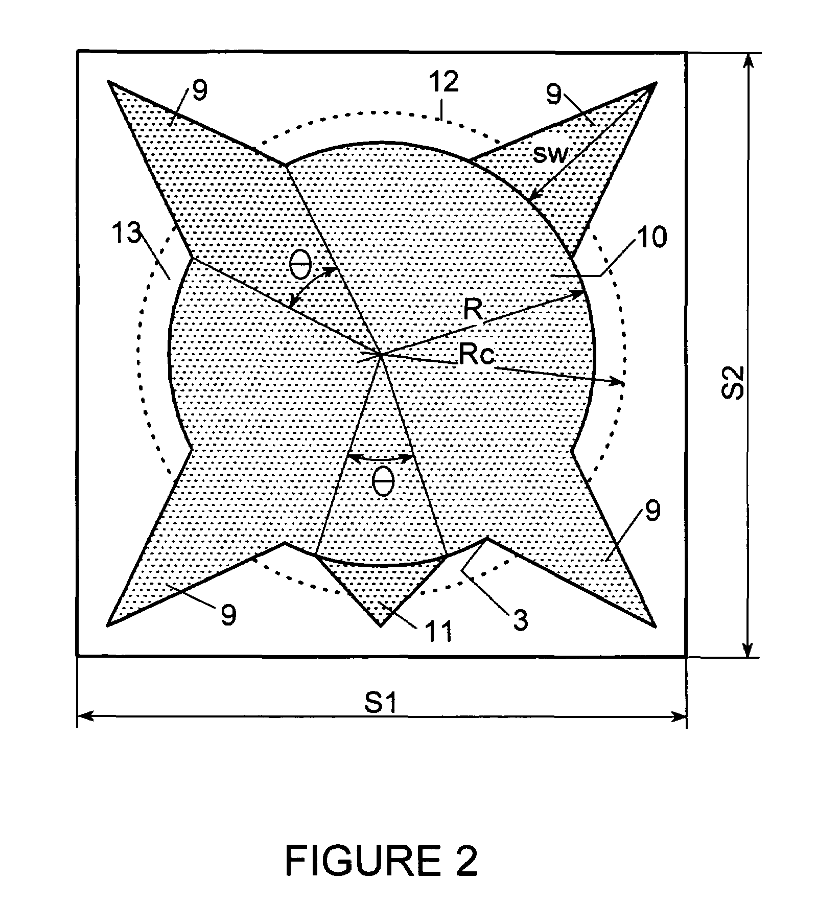
[0050]FIG. 2 shows a cross-sectional view of a mixer according to the invention positioned within a square duct.

[0051]FIG. 3 shows a graph describing degree of mixing as a function of pressure loss for a mixing device according to the invention with respect to a conventional circular mixing device.

[0052]In FIG. 1 the flue gas section for reduction of nitrogen oxides comprises a duct 1 having rectangular section through which a flue gas 2 passes. The flue gas represents a first major fluid stream travelling in direction Z and collides with the front side of mixing device 3, which is disposed substantially transversally to the travelling direction of said first major fluid stream. Mixer 3 is positioned at incidence angle α with respect to the travelling direction of the major fluid stream 2. A second fluid...


PUM


Abstract

A method for the mixing of fluid streams in a duct comprising positioning at least one mixing device having a front side and a back side within said duct through which a first major stream travels, the at least one mixing device determining a total cross-sectional area which is significantly lower than that of the duct so as to allow for the passage of said first major stream, whereby the at least one mixing device is a solid plate provided with one or more protrusions extending outward from the main solid plate body.

Description

FIELD OF THE INVENTION[0001]The present invention relates to a method for the mixing of fluid streams in a duct, with at least one mixing device being positioned within said duct and in particular the invention relates to a novel mixing device for such a method.[0002]The invention relates particularly to a method for the mixing of fluid stream suitable for use in applications including reduction of nitrogen oxides and reduction of sulphuric acid from acid mist in flue gas cleaning.BACKGROUND OF THE INVENTION[0003]The proper mixing of single fluid streams or several fluid streams that interact in ducts or channels requires the presence of relatively turbulent regions by the generation of velocity components transverse to the main major fluid stream passing through the duct. In order to achieve proper mixing between for instance one or more fluid streams being injected into a major fluid stream, a certain distance along the duct (channel) is required. Conventionally, this is quantifie...

Claims


Application Information

Patent Timeline
Patent Type & Authority Patents(United States)
IPC IPC(8): B01F5/00B01F5/04B01F5/06F17D1/00
CPCB01F5/0451B01F5/0453B01F5/0458B01F5/0616Y10T137/87652B01F25/31323B01F25/3131B01F25/3132B01F25/4315
Inventor HANSEN, MICHAEL BO
Owner UMICORE AG & CO KG
Why Eureka
Try Eureka