Mold for glass substrate molding, method for producing glass substrate, method for producing glass substrate for information recording medium, and method for producing information recording medium

a technology of glass substrate and molding method, which is applied in the direction of glass making apparatus, dough shaping, manufacturing tools, etc., can solve the problems of high sulphur content of effluent, high cost and inconvenience of forming briquettes, and iron waste, so as to achieve high energy efficiency, reduce surface area loss, and heat the melt homogeneously

Active Publication Date: 2010-05-06
ROCKWOOL AS
View PDF6 Cites 26 Cited by
  • Summary
  • Abstract
  • Description
  • Claims
  • Application Information

AI Technical Summary

Benefits of technology

[0038]In the bottom section of the circulating combustion chamber the mineral melt flows down the walls to be collected in the base section. In this region the melt is present as a thin film on the walls of the chamber and as a bath in the base section, which is normally shallow. Hence, applying radiant heat in this area is particularly effective as it can penetrate the whole of the melt easily. Therefore, using a flame in this region is particularly effective at heating the melt homogeneously. It can also heat the melt rapidly and precisely so that by varying the flow rate of secondary fuel and secondary combustion gas, the temperature of the melt can be maintained within precise limits.
[0039]In contrast, in prior art systems the temperature of the melt is not controlled in the chamber. Where the melt is not collected in the bottom of the chamber, but is collected in a separate (usually larger) tank, it would not be po...

Problems solved by technology

Accordingly, if the material which is available is only available in finely divided form, it is necessary to incur the expense and inconvenience of forming it into briquettes.
Briquetting usually uses sulphur-containing materials as binder, such as Portland cement with gypsum, and this means that the effluent is liable to have a high sulphur content, which has to be treated.
The cupola or other stack furnace system also has the disadvantage that conditions in the furnace always tend to be sufficiently reducing that some of the iron is reduced to metallic iron.
This necessitates separating metallic iron from the melt, reduces wool production, leads to t...

Method used


Image

  • Mold for glass substrate molding, method for producing glass substrate, method for producing glass substrate for information recording medium, and method for producing information recording medium
  • Mold for glass substrate molding, method for producing glass substrate, method for producing glass substrate for information recording medium, and method for producing information recording medium

Examples


example

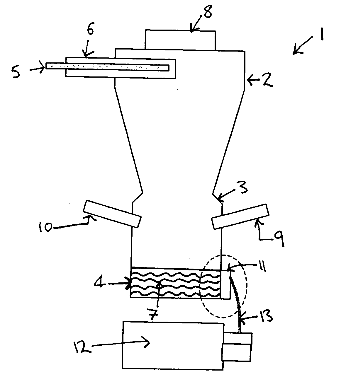
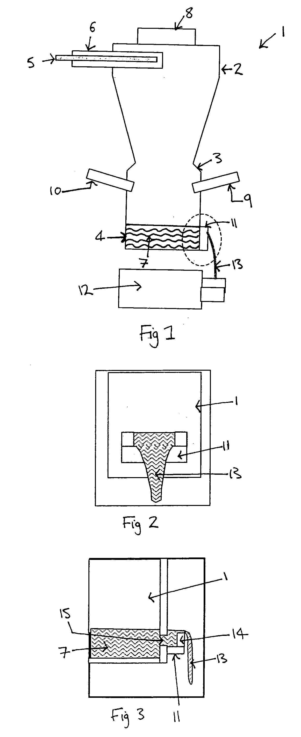
[0104]The inventors have demonstrated that providing fuel as secondary fuel into the bottom section of the circulating combustion chamber is a very efficient way to increase the melt temperature. In the tests performed, the total amount of fuel energy (primary and secondary) into the cyclone was increased by 2%. The extra fuel was added as secondary fuel provided at the bottom of the chamber. The amount of primary fuel was kept constant. This led to an increase in the melt temperature of 40-50° C.

[0105]To achieve the same temperature rise of the melt in a cupola furnace, much more than 2% extra energy would be needed.

[0106]The high efficiency of the present invention is due to the fact that adding fuel energy in the bottom section can rapidly and efficiently heat the thin layer of melt running down the sides of the chamber and in the base of the chamber.


PUM

PropertyMeasurementUnit
Fractionaaaaaaaaaa
Fractionaaaaaaaaaa
Fractionaaaaaaaaaa

Abstract

The present invention relates to a method of making mineral fibres, comprising providing a circulating combustion chamber (1) which comprises a top section (2), a bottom section (3) and a base section (4), injecting primary fuel, particulate mineral material and primary combustion gas into the top section of the circulating combustion chamber and combusting the primary fuel thereby melting the particulate material to form a mineral melt and generating exhaust gases, separating the mineral melt from the exhaust gases wherein the exhaust gases pass through an outlet (8) in the circulating combustion chamber and the mineral melt collects in the base section of the circulating combustion chamber, injecting secondary fuel, which comprises liquid or gaseous fuel, and secondary combustion gas into the bottom section of the circulating combustion chamber to form a flame in the bottom section which heats the melt, and flowing a stream of the collected melt through an outlet (15) in the base section to a centrifugal fiberising apparatus and forming fibres. The present invention also provides an apparatus for use in the method of the invention.

Description

BACKGROUND TO THE INVENTION[0001]This invention relates to the production of a mineral melt by burning combustible material in the presence of inorganic particulate material and thereby forming a melt. The melt is then fiberised to form mineral fibres.[0002]Traditionally, the normal way of producing a melt for slag, stone or rock fibres has been by means of a shaft furnace in which a self-supporting stack of inorganic particulate material is heated by combustion of combustible material in the furnace. The stack gradually melts and is replenished from the top, with melt draining down the stack and out from the bottom of the furnace. The normal furnace for this purpose is a cupola furnace.[0003]It is necessary for the stack to be self-supporting and permeable to the combustion gases, which are generally generated by combustion of carbonaceous material in the stack. It is therefore necessary that everything in the stack is relatively coarse (in order that the stack is permeable) and ha...

Claims


Application Information

Patent Timeline
IPC IPC(8): B28B1/20
CPCC03B5/12C03B5/235Y02P40/55Y02P40/57C03B5/2353Y02P40/50
Inventor HANSEN, LARS ELMEKILDEBOELLUND, LARSHANSEN, LARS KRESTENHANSEN, PETER FARKAS BINDERCUPJENSEN, LEIF MOELLER
Owner ROCKWOOL AS
Why Eureka
Try Eureka