Honeycomb structure and honeycomb catalytic body

a honeycomb and catalytic body technology, applied in the direction of metal/metal-oxide/metal-hydroxide catalysts, machines/engines, chemical/physical processes, etc., can solve the problems of high pressure loss, difficult mounting, and ininverse proportion of the square of the hydraulic diameter of the cell, so as to achieve excellent purification efficiency and reduce pressure loss. , the effect of excellent purification efficiency

Active Publication Date: 2007-03-08
NGK INSULATORS LTD
View PDF8 Cites 22 Cited by
  • Summary
  • Abstract
  • Description
  • Claims
  • Application Information

AI Technical Summary

Benefits of technology

[0027] A honeycomb structure of the present invention is effective in providing a honeycomb catalyst body having excellent purification efficiency, low pressure loss, and mountability even in a limited space.
[0028] In addition, a honeycomb catalyst body of the present invention is effective in having excellent purification efficiency, low pressure loss, and mountability even in a limited space.

Problems solved by technology

However, pressure loss also tends to increase in inverse proportion to the square of a hydraulic diameter of the cells.
Therefore, there arises a problem that pressure loss rises in accordance with rise in transmissibility of target components.
However, in the case that the honeycomb catalyst body is enlarged, it sometimes makes mounting difficult because of the limited mounting space regarding, for example, a honeycomb catalyst body to be mounted on a vehicle.

Method used


Image

  • Honeycomb structure and honeycomb catalytic body
  • Honeycomb structure and honeycomb catalytic body
  • Honeycomb structure and honeycomb catalytic body

Examples


example

[0081] The present invention will hereinbelow be described in more detail on the basis of Examples. However, the present invention is by no means limited to these Examples.

[0082] [Average Image Maximum Distance]

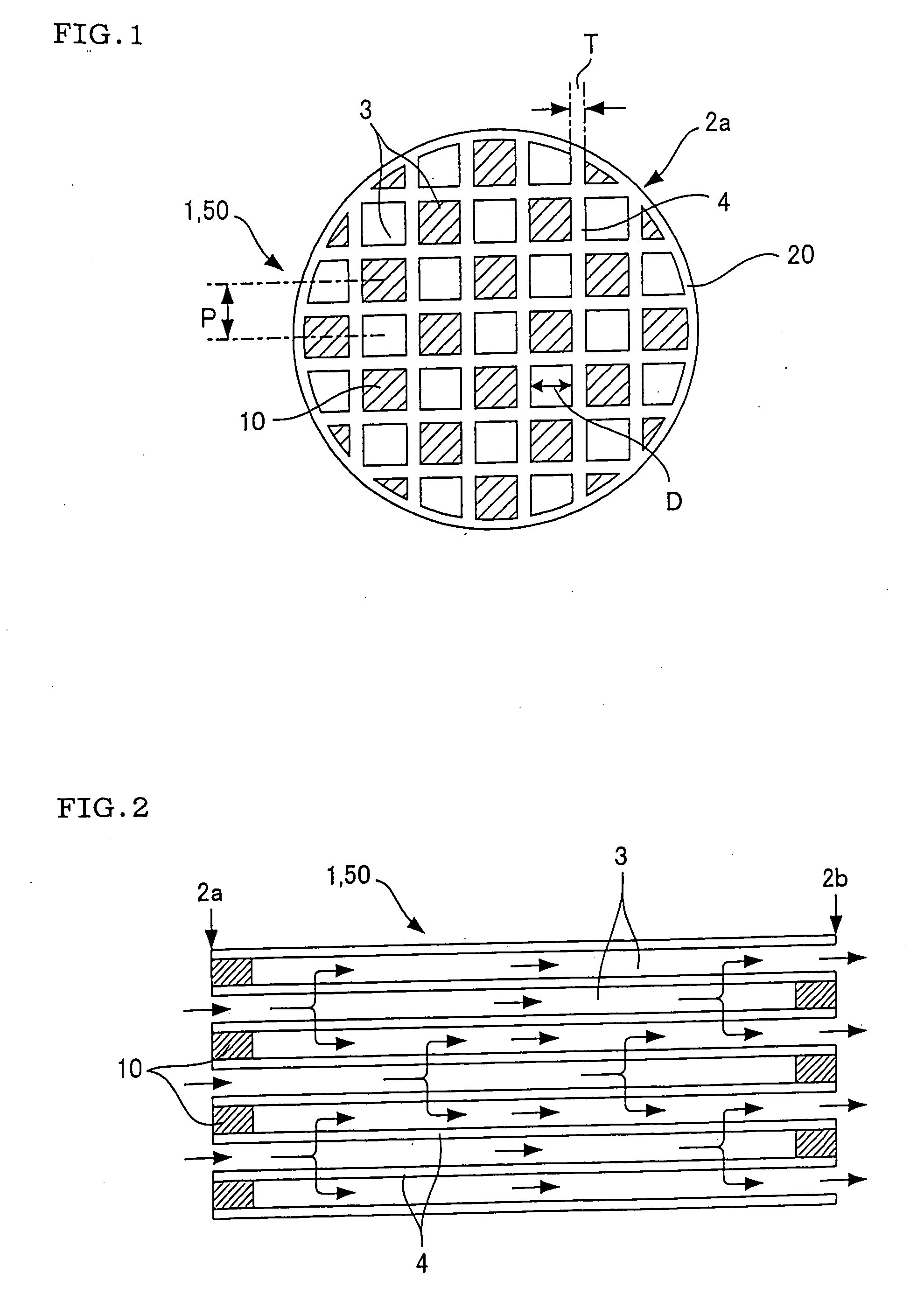
[0083] Pore diameters were measured by image analysis, and the average image maximum distance was calculated. Concretely, a SEM photograph of a cross-section of a partition wall was observed for at least 20 viewing fields with respect to a viewing field of length×width=t×t in the case that the partition wall thickness was defined as “t”. Next, the maximum linear distance in a gap was measured within each of the viewing fields observed above, and the average value of the maximum linear distances measured with respect to all the viewing fields was determined as the “average image maximum distance”.

[0084] [Standard Deviation (σ) of Pore Diameter Distribution]

[0085] A pore diameter distribution was measured by the use of a mercury porosimeter (Trade name: Auto Pore III, type 94...

examples 1 to 24

, Comparative Examples 1, 2

[0103] To 100 parts by mass of a cordierite forming raw material prepared by combining some selected from talc, kaolin, calcined kaolin, alumina, calcium hydroxide, and silica at a predetermined ratio to have the chemical composition of 42 to 56% by mass of SiO2, 0 to 45% by mass of Al2O3, and 12 to 16% by mass of MgO, were added 12 to 25 parts by mass of graphite as a pore former and 5 to 15 parts by mass of a synthetic resin. To the mixture were further added an appropriate amount of a methyl cellulose and a surfactant. Then, water was further added to the mixture, and the mixture was kneaded to prepare clay. The clay was subjected to vacuum degassing and subsequently to extrusion forming to obtain honeycomb formed bodies. After the honeycomb formed bodies were dried, they were fired at the highest temperature of 1400 to 1430° C. to obtain honeycomb fired bodies. By plugging one of the end portions of each cell of the obtained honeycomb fired bodies to g...

example 25

[0105] A honeycomb structure having a pore structure of partition walls shown in Table 2, a diameter of 144 mm, and a length of 152 mm was manufactured in the same manner as in the above Examples 1 to 24 and Comparative Examples 1 and 2 except that a chemical composition of the cordierite forming material, a particle diameter of the pore former, an amount of the pore former added, and the like, are suitably adjusted. A percentage of the number of carbon particulates passing through the honeycomb structure is shown in Table 2.


PUM

PropertyMeasurementUnit
concentrationaaaaaaaaaa
diameteraaaaaaaaaa
diameteraaaaaaaaaa

Abstract

A honeycomb structure includes: porous partition walls having a large number of pores and disposed to form a plurality of cells communicating between two end faces, and plugged portions disposed to plug each of the cells on one of the end faces. A percentage of the number of carbon particulates contained in combustion exhaust gas satisfying the following condition (1) and passing through a honeycomb structure is 80% or more at a space velocity of 25000/h. The condition (1) is that the carbon particulates has a mean diameter of 0.07 to 0.2 μm, a ratio of the carbon particulates having a diameter of 1 μm or more is 0.1% or less in number and that a concentration of the carbon particulates is 10 mg/m3. The honeycomb structure is excellent in purification efficiency, has low pressure loss, and is mountable even in a limited space.

Description

BACKGROUND OF THE INVENTION AND RELATED ART STATEMENT [0001] The present invention relates to a honeycomb structure suitably usable for purifying target components such as carbon monoxide (CO), hydrocarbonate (HC), nitrogen oxides (NOx), and sulfur oxides (SOx) contained in exhaust gas discharged from stationary engines for automobiles, construction machines, and industry and combustion apparatuses and to a honeycomb catalyst body. [0002] At present, a honeycomb structured catalyst body (honeycomb catalyst body) is used for purifying exhaust gas discharged from various kinds of engines, or the like. As shown in FIG. 6, the honeycomb catalyst body has a structure where a catalyst layer 15 is loaded on a surface of partition walls 4 forming cells 3. In addition, as shown in FIGS. 4 and 5, when exhaust gas is purified by the use of the honeycomb catalyst body 60 (honeycomb structure 11) , exhaust gas is allowed to flow into the cells 3 of the honeycomb catalyst body 60 from one end fac...

Claims


Application Information

Patent Timeline
Patent Type & Authority Applications(United States)
IPC IPC(8): B01J21/04
CPCB01D46/2425Y02T10/20B01D46/2451B01D46/2466B01D46/247B01D46/2474B01D2046/2433B01D2046/2496B01J21/14B01J23/63B01J35/04C04B38/0009C04B2111/00793C04B2111/0081F01N3/0222F01N3/035F01N2260/06B01D46/2429C04B35/00C04B38/0054C04B38/0074Y02T10/12B01D46/24491B01D46/2498B01D46/2484B01D46/2482B01D46/24492
Inventor MIYAIRI, YUKIO
Owner NGK INSULATORS LTD
Why Eureka
Try Eureka