Cyclone dust collector

a dust collector and cyclone technology, applied in the field of cyclone dust collectors, can solve the problems of reducing the workability temperature of exhaust gas, excessive amounts of waste water, and reducing the workability of electrostatic precipitators, so as to reduce friction loss in the collector body due to rotational flow, reduce the flow rate of swirling inside the collector body, and reduce the effect of pressure loss

Active Publication Date: 2014-02-25
KOREA INST OF ENERGY RES
View PDF12 Cites 24 Cited by
  • Summary
  • Abstract
  • Description
  • Claims
  • Application Information

AI Technical Summary

Benefits of technology

[0027]The present invention as described above shows dust collecting efficiency equal to or better than the efficiency of conventional cyclones and has an effect of relatively very low pressure loss. Since a certain amount of inlet flow is devided by and passes through slits and consequently the flow rate swirling inside the collector body is reduced, the friction loss in the collector body due to rotational flow is reduced. That is, a pressure drop of the cyclone can be reduced. The cyclone of the present invention has a dust particle collecting efficiency equal to the conventional cyclone and has effect of reducing pressure loss as much as 10˜90% compared to the conventional cyclone. Further, through the double wall structure with the collector body and the collector housing, some of abrasion problem in the conventional cyclone can be solved.

Problems solved by technology

The wet method has a high dust collecting efficiency but produces excessive amounts of waste water.
However, the electrostatic precipitator has a limitation in workable temperature of exhaust gas and a demerit of expensive facilities cost.
The dust collector using bag filter has 98% dust collecting efficiency but has a problem of limited workable temperature.
However, when applied as primary dust collector in front of an electrostatic precipitator collector or bag filters, the whole pressure loss becomes very high and increases the operation cost.
Further, if the conventional cyclone is applied to remove abrasive dust particles, the cyclone is easily worn out and its lifespan is decreased.
In this case, an inner wall of the cyclone dust collector has to be reinforced with anti-abrasive material causing increase of cost for facilities.

Method used


Image

  • Cyclone dust collector
  • Cyclone dust collector
  • Cyclone dust collector

Examples


Embodiment Construction

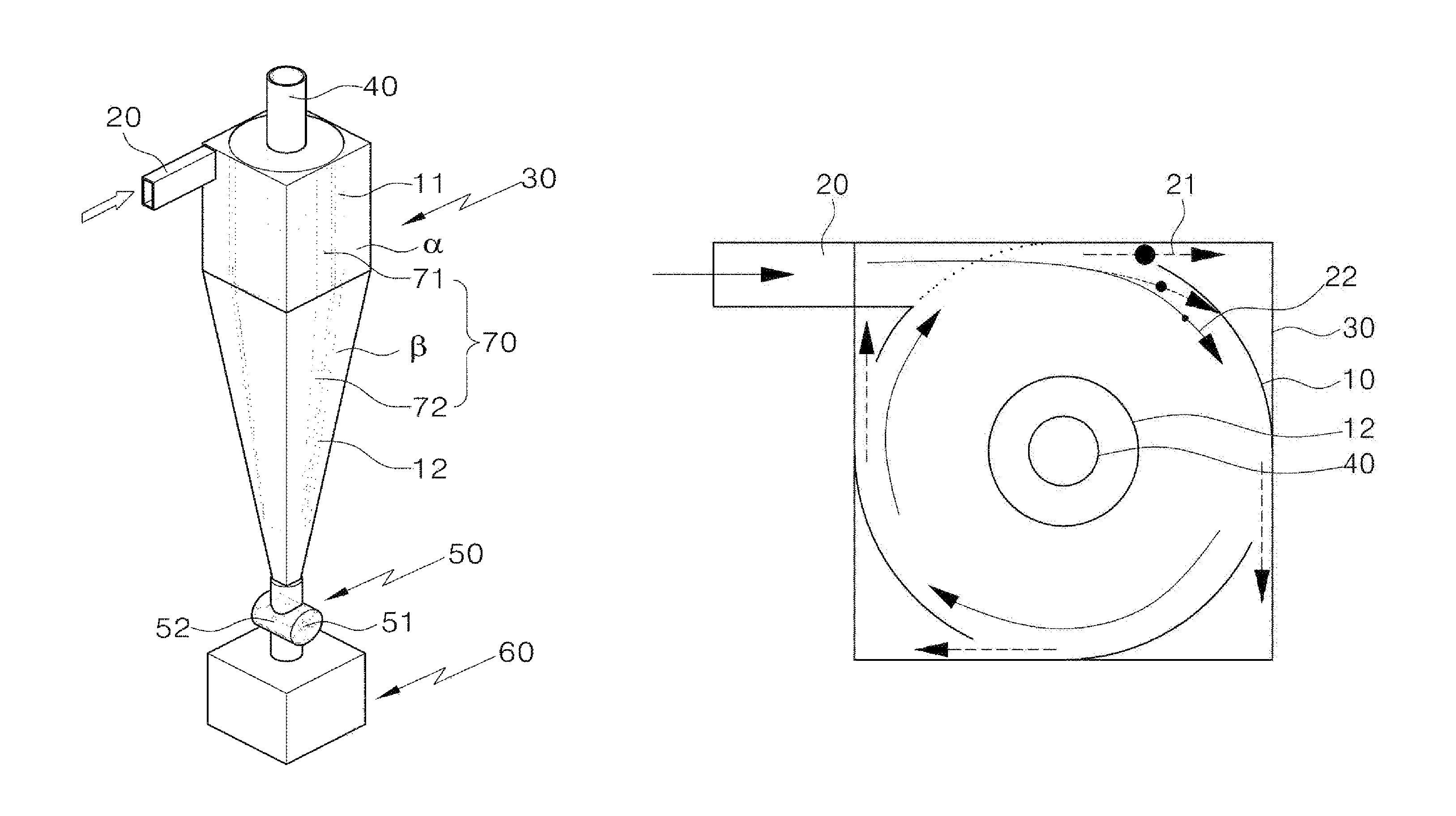
[0055]Before describing several embodiments of the present invention, it will be understood that a detail description of configuration or arrangements of element members recited in the detailed description or illustrated in drawings shall not limit their application. The present invention may be realized by other embodiments and may be performed in various methods. Further, it will be understood that expressions and terms related with direction (for example “front”, “back”, “up”“down”, “top”, “bottom”, “left”, “right”“lateral”, etc.) of the dust collector or elements are used to simplify description for the present invention but not meant to represent that the related apparatus or elements should be directed in certain directions.

[0056]The present invention has following features to achieve the said objects.

[0057]The present invention will now be described more fully hereinafter with reference to the accompanying drawings. It will be understood that words or terms used in the specif...


PUM

PropertyMeasurementUnit
diameteraaaaaaaaaa
depthaaaaaaaaaa
heightaaaaaaaaaa

Abstract

A cyclone dust collector having a single or multiple dust collection bodies installed within a housing, wherein the dust collection body is composed of an upper primary cylindrical dust collection part and a lower secondary conical duct collection part, and a single or multiple slits are cut in the wall surfaces of the primary and secondary dust collection parts in such a manner that large dust particles with large inertial force are removed between the dust collection housing and the dust collection body via the slit(s), while small dust particles with small inertial force make a swirling flow motion within the dust collection body and are removed by the centrifugal force.

Description

TECHNICAL FIELD[0001]The present invention relates to a cyclone dust collector that removes dust particles in dirty gas by separating dust particles from dirty gas using inertial force and centrifugal force.BACKGROUND ART[0002]A cyclone dust collector is an apparatus that collects and removes fine liquid or solid particles in gas stream. The dust collector uses a principle that, if dust laden gas is applied with acceleration much larger than gravity, a separating velocity of dust particles from gas becomes larger compared to a settling velocity by weight. A structure of conventional cyclone dust collector is shown in FIG. 1. The conventional apparatus provides a structure with: a main body (100) integrated vertically with a storage tank (130) installed at its bottom; a gas inlet (110) formed at one side horizontally along a tangential direction from an outer wall at an upper part of the main body to communicate with the inside of the main body; and an outlet (120) inserted into the ...

Claims


Application Information

Patent Timeline
Patent Type & Authority Patents(United States)
IPC IPC(8): B01D51/00
CPCA47L9/1683B04C5/081B04C5/28B04C5/10A47L9/16B04C3/04
Inventor PARK, HYUN SEOLLIM, KYOUNG SOO
Owner KOREA INST OF ENERGY RES
Why Eureka
Try Eureka