
Combustion method and burner for carrying out the method

a combustion method and burner technology, applied in the field of combustion technology, can solve the problems of considerable pressure drop, insufficient increase of gas temperature, and insufficient thermal stabilization of the combustion of the fuel which remains at the outlet of the catalytic reactor

Active Publication Date: 2005-05-24
ANSALDO ENERGIA SWITZERLAND AG
View PDF16 Cites 22 Cited by
  • Summary
  • Abstract
  • Description
  • Claims
  • Application Information

AI Technical Summary

Benefits of technology

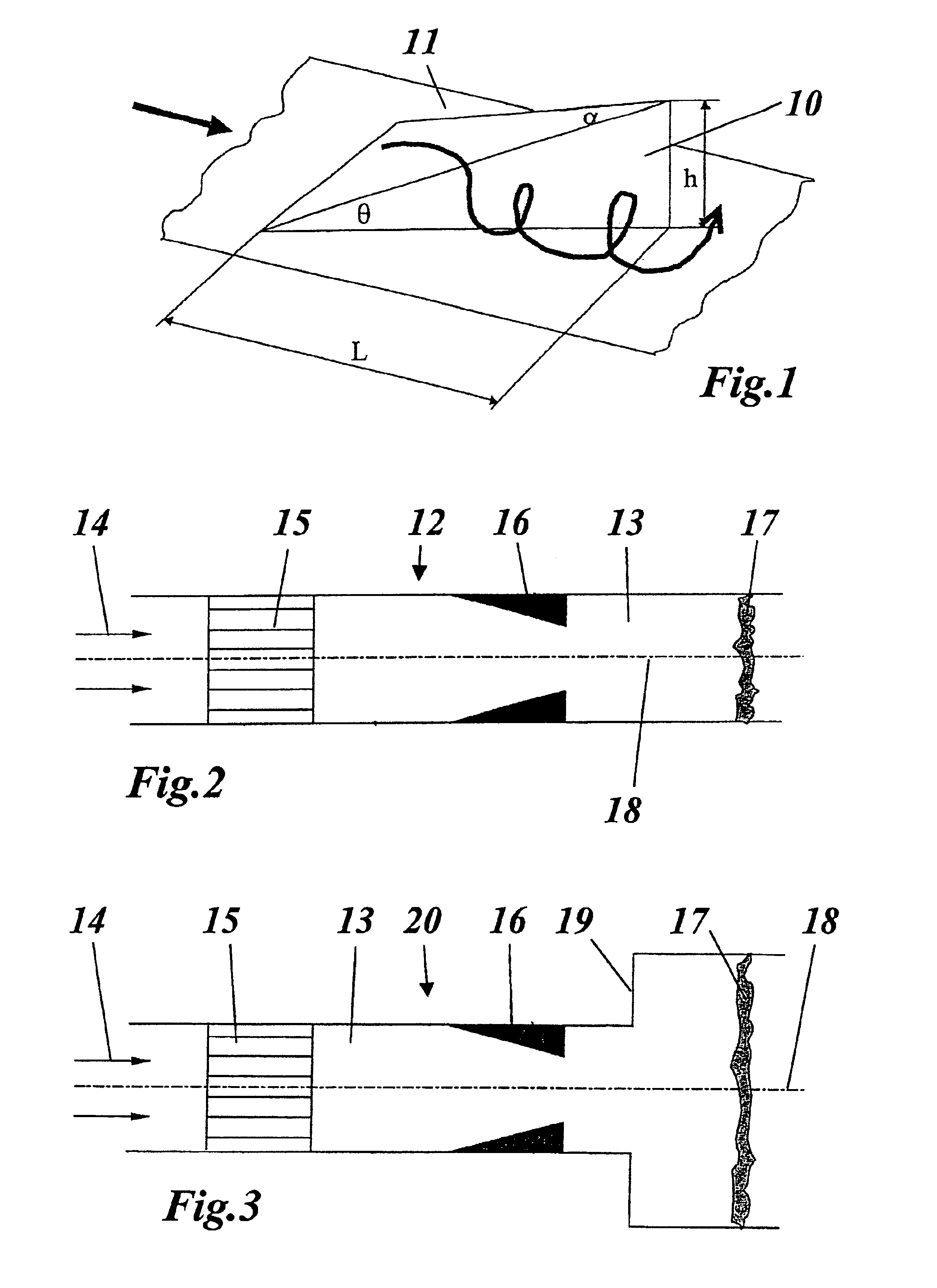
[0009]Accordingly, one object of the invention is to provide a novel two-stage combustion method with catalytic reactor in the first combustion stage, which is simple and reliable to carry out and leads to lower pressure losses, and to provide a burner for carrying out the method.
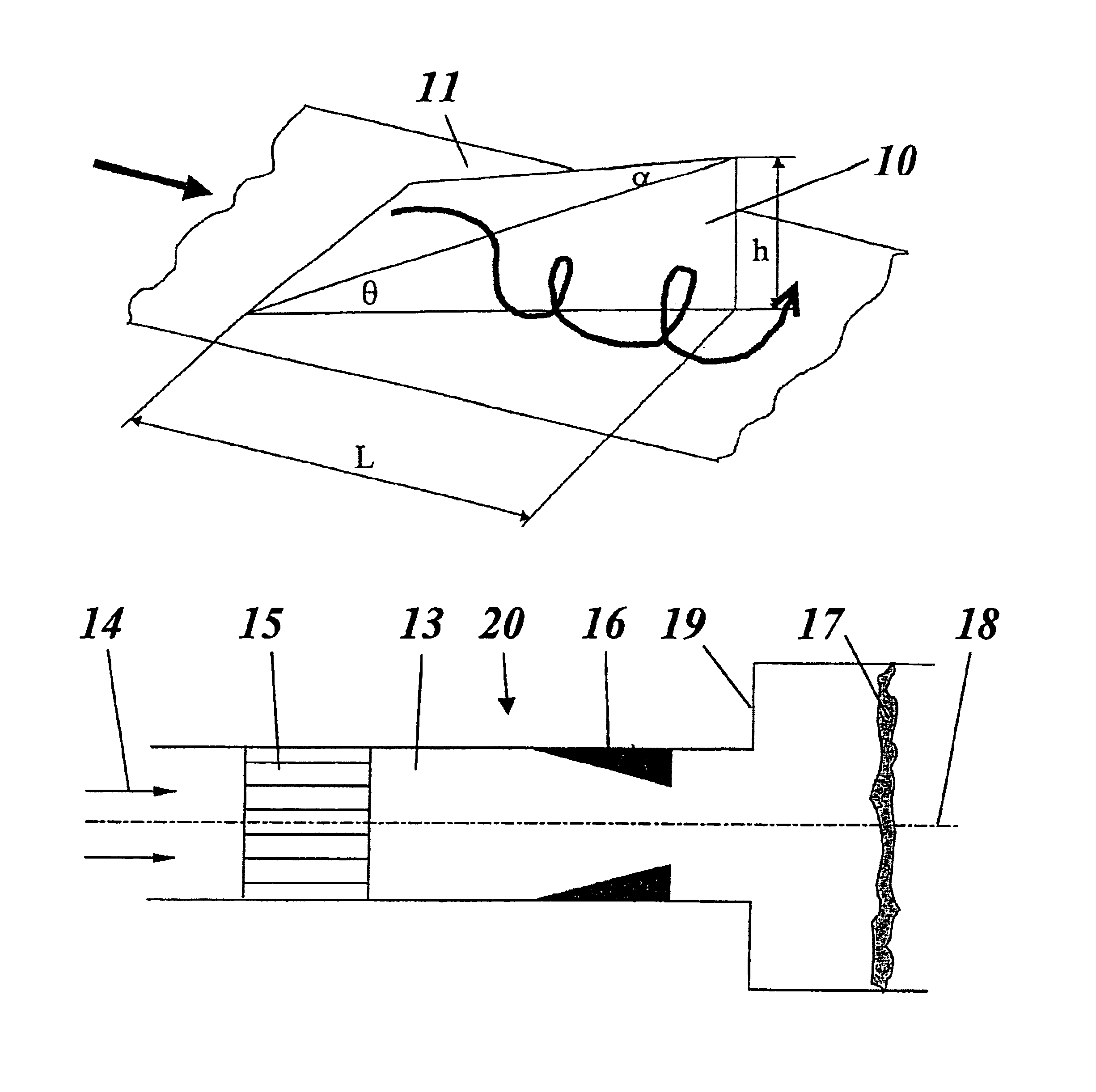
[0017]Furthermore, it is advantageous if the formation of the vortex generators is dependent on whether the vortex generators are intended primarily for mixing or for vortex breakdown.

Problems solved by technology

Therefore, the gas temperature which results may not be sufficiently increased to thermally stabilize the combustion of the fuel which remains at the outlet of the catalytic reactor (and comprises a homogenous mixture of fuel, O2, N2, CO, CO2, and H2O at temperatures between 600° C. and 950° C.).
However, this technique only works at relatively high temperatures at the catalytic reactor outlet.
However, if greater dynamic stabilization is required, this can be achieved by the formation of highly swirled flows which promote vortex breakdown.
However, a large-volume vortex of this nature requires relatively complex devices which cause considerable pressure drops.

Method used


Image

  • Combustion method and burner for carrying out the method
  • Combustion method and burner for carrying out the method

Examples


Embodiment Construction

[0022]Referring now to the drawings, wherein light reference numerals designate identical or corresponding parts throughout the several views, it is proposed for what are known as SEV vortex generators to be used to aerodynamically stabilize the homogenous flames in particular with respect to the catalytic burner. The result of this method is that:[0023]sufficient flame stabilization is achieved irrespective of the outlet temperature at the catalytic reactor, so that operation is possible even if the outlet temperature at the catalytic reactor is low;[0024]the pressure drop is minimized; and[0025]flow and temperature fields are made more uniform toward the turbine inlet and profit from the increased mixing of the vortex flows.

[0026]Furthermore, the use of SEV vortex generators is advantageous because there is already extensive experience available relating to the design of these elements (in terms of cooling, fatigue, flame position, pulsation, velocity and temperature distribution)...


PUM


Abstract

In a combustion method, in a burner (12, 20), a fuel / air mixture flowing through a flow passage (13) is made to react in a first combustion stage in a catalytic reactor (15), and downstream of the catalytic reactor (15) fuel is burnt together with the exhaust gas from the catalytic reactor (15) in a second combustion stage to form a homogenous flame (17) by self-ignition.If the fuel from the fuel / air mixture is only partially burnt in the first combustion stage in the catalytic reactor (15), and the unburnt remainder of the fuel is burnt in the second combustion stage, combustion can be stabilized by virtue of the fact that the fuel-containing exhaust gas from the catalytic reactor (15), between the outlet of the catalytic reactor (15) and the homogenous flame (17) is passed through devices 916, 19) which aerodynamically stabilize the homogenous flame (17).

Description

BACKGROUND OF THE INVENTION[0001]1. Field of the Invention[0002]The present invention deals with the field of combustion technology. It relates to a combustion method in accordance with the preamble of claim 1 and to a burner for carrying out the method.[0003]2. Discussion of Background[0004]Catalytic combustion is a method which can be used in gas turbines to increase the stability of the combustion process and to reduce the levels of emission (cf. for example U.S. Pat. No. 6,339,925 B1). Limits on the load which can be applied to materials and on the operating conditions require the catalytic reactors used to convert only part (typically up to 60%) of the total amount of fuel flowing through the burner. Therefore, the gas temperature which results may not be sufficiently increased to thermally stabilize the combustion of the fuel which remains at the outlet of the catalytic reactor (and comprises a homogenous mixture of fuel, O2, N2, CO, CO2, and H2O at temperatures between 600° C...

Claims


Application Information

Patent Timeline
IPC IPC(8): F23C13/00F23R3/40F23R3/00F23D14/02F23D14/18F23R3/12
CPCF23R3/40F23C13/00
Inventor CARRONI, RICHARDFLOHR, PETER
Owner ANSALDO ENERGIA SWITZERLAND AG
Learn More