Transition duct apparatus having reduced pressure loss

a technology of transition duct and pressure loss, which is applied in the direction of lighting and heating apparatus, machines/engines, stators, etc., can solve the problems of high cost of gas turbine operation, high cost of gas turbine fuel burning, maintenance cost, etc., and achieve the effect of reducing the pressure loss of the cooling air

Active Publication Date: 2006-11-21
ANSALDO ENERGIA SWITZERLAND AG
View PDF8 Cites 25 Cited by
  • Summary
  • Abstract
  • Description
  • Claims
  • Application Information

AI Technical Summary

Benefits of technology

[0007]It is an object of the present invention to provide a gas turbine transition duct that creates a lower pressure loss to the cooling air.

Problems solved by technology

In addition to maintenance costs, one of the highest costs associated with operating a gas turbine at a powerplant, is the cost of the fuel burned in the gas turbine, either gas, liquid, or coal.
Often times cooling air is not used in the most efficient manner with regards to limiting the amount of pressure loss that occurs when cooling the transition duct.
As a result an unnecessary drop in supply pressure to the turbine occurs, yielding a lower turbine efficiency and engine performance.

Method used


Image

  • Transition duct apparatus having reduced pressure loss
  • Transition duct apparatus having reduced pressure loss
  • Transition duct apparatus having reduced pressure loss

Examples


Embodiment Construction

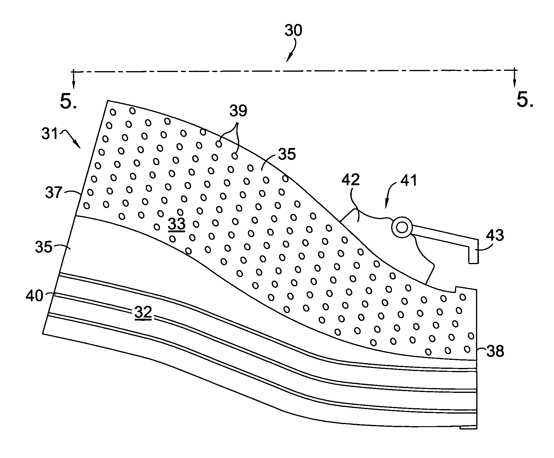
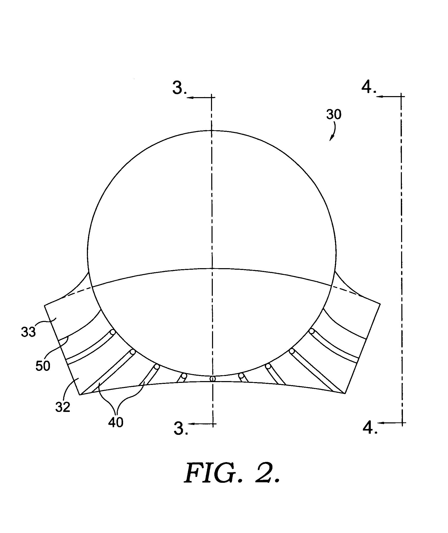
[0015]A gas turbine transition duct having reduced pressure loss is disclosed in detail in FIGS. 2–5. Transition duct 30 comprises a panel assembly 31, where panel assembly 31 further comprises a first panel 32 and a second panel 33, each of which are formed from a single sheet of metal. First panel 32 is fixed to second panel 33 by a means such as welding along a seam 50 to form a duct having an inner surface 34 and an outer surface 35, thereby forming a thickness 36 therebetween, a generally cylindrical inlet end 37, and a generally rectangular exit end 38. In order to withstand the elevated operating temperatures from the hot combustion gases passing through the transition duct, duct 30 is typically a high temperature alloy with thickness 36 at least 0.062 inches. In addition to panel assembly 31, transition duct 30 also comprises a plurality of first holes 39 located in second panel 33 of panel assembly 31. First holes 39 provide cooling, typically with air, through thickness 36...


PUM


Abstract

A gas turbine transition duct having a reduced pressure loss is disclosed. The transition duct of the preferred embodiment comprises a panel assembly having a first panel fixed to a second panel and a mounting assembly for securing the transition duct to a turbine inlet. The first panel includes a means for augmenting the heat transfer from the first panel while the second panel includes a plurality of first cooling holes for directing cooling air through the second panel. Specific details are provided regarding the first cooling holes and multiple embodiments are disclosed for the heat transfer augmentation of the transition duct first panel.

Description

TECHNICAL FIELD[0001]This invention primarily applies to gas turbine engines used to generate electricity and more specifically to a transition duct for directing hot combustion gases from a combustor to a turbine inlet.BACKGROUND OF THE INVENTION[0002]Operators of gas turbine engines used in generating electricity at powerplants desire to have the most efficient operations possible in order to maximize their profitability and limit the amount of emissions produced and excess heat lost. In addition to maintenance costs, one of the highest costs associated with operating a gas turbine at a powerplant, is the cost of the fuel burned in the gas turbine, either gas, liquid, or coal. Increasing the efficiency of the gas turbine will result in an increase in electrical generation capacity for a given amount of fuel burned. Alternatively, if additional electrical generation is not possible or desired, the required level of electricity can be generated at a lower fuel consumption rate. Unde...

Claims


Application Information

Patent Timeline
Patent Type & Authority Patents(United States)
IPC IPC(8): F02C3/14F02C7/18F01D9/02F23R3/00F23R3/42
CPCF01D9/023F23R3/002F23R2900/03041F05D2260/202F05D2260/221F05D2260/203
Inventor MARTLING, VINCENT C.XIAO, ZHENHUA
Owner ANSALDO ENERGIA SWITZERLAND AG
Why Eureka
Try Eureka