Method of loading solid particles into a fixed-bed multitubular reactor

a multi-tubular reactor and solid particle technology, applied in the direction of physical/chemical process catalysts, liquid handling, metal/metal-oxide/metal-hydroxide catalysts, etc., can solve the problems of significant reduction of the amount of the catalyst to be engaged in the reaction, the impact of solid particle disruption, and the impact of catalyst life reduction, etc., to achieve stably the effect of reducing the variability of pressure loss among the reaction tubes, reducing the amount of solid particles, and reducing the impact of the effect o

Inactive Publication Date: 2011-01-27
NIPPON SHOKUBAI CO LTD
View PDF17 Cites 22 Cited by
  • Summary
  • Abstract
  • Description
  • Claims
  • Application Information

AI Technical Summary

Benefits of technology

[0011]According to the present invention, powdered particles generated upon loading the solid particles can be easily removed from the reaction tubes; and as a result, a pressure loss of the fixed-bed multitubular reactor becomes low, the pressure loss can be easily adjusted, increase of the pressure loss and variability of the pressure loss among the reaction tubes with time can be suppressed, and a target product can be stably obtained at a high yield for a long period by using the fixed-bed multitubular reactor.

Problems solved by technology

In this method, however, a part of the solid particles may be disrupted or powdered due to physical impact upon dropping, and powdered particles resulting therefrom may increase a pressure loss or cause a substantive reduction of the amount of a catalyst to be engaged in a reaction.
In addition, the powdered particles may cause a reduction of a yield of a target product or a catalyst lifetime.
Moreover, the powdered particles may cause blockage of the reaction tubes due to by-products resulting from a nonuniform reaction in the reactor.

Method used


Image

  • Method of loading solid particles into a fixed-bed multitubular reactor
  • Method of loading solid particles into a fixed-bed multitubular reactor
  • Method of loading solid particles into a fixed-bed multitubular reactor

Examples


reference example 1

[0043](Preparation of Catalyst) 1,500 parts of distilled water was heated and stirred, and 500 parts of ammonium paramolybdate was dissolved therein to give a solution A. Separately, 398 parts of cobalt nitrate and 199 parts of nickel nitrate were dissolved in 500 parts of distilled water to give a solution B. Further separately, 25 parts of concentrated nitric acid (65%) was added to 100 parts of distilled water to give an acidic solution, and 137 parts of bismuth nitrate and 95 parts of ferric nitrate were dissolved therein to give a solution C. The solutions B and C were added dropwise to the solution A, and then, to the obtained mixture, 3.6 parts of potassium nitrate and 126 parts of tungsten trioxide were added. The thus obtained slurry was heated and stirred to vaporize the solvent. The resultant dry product was dried at 200° C. and then pulverized to 150 μm or less to give a catalyst powder. 30 mass % ammonium nitrate aqueous solution was added to the catalyst powder, and th...

reference example 2

[0044]A catalyst (2) was obtained in the same manner as in Reference Example 1, except that the product was extrusion-molded into a ring shape having an outer diameter of 8 mm, an inner diameter of 2.5 mm, and a length of 8 mm in Reference Example 1. The metal element composition of the catalyst (2) was same as that of the catalyst (1).

example 1

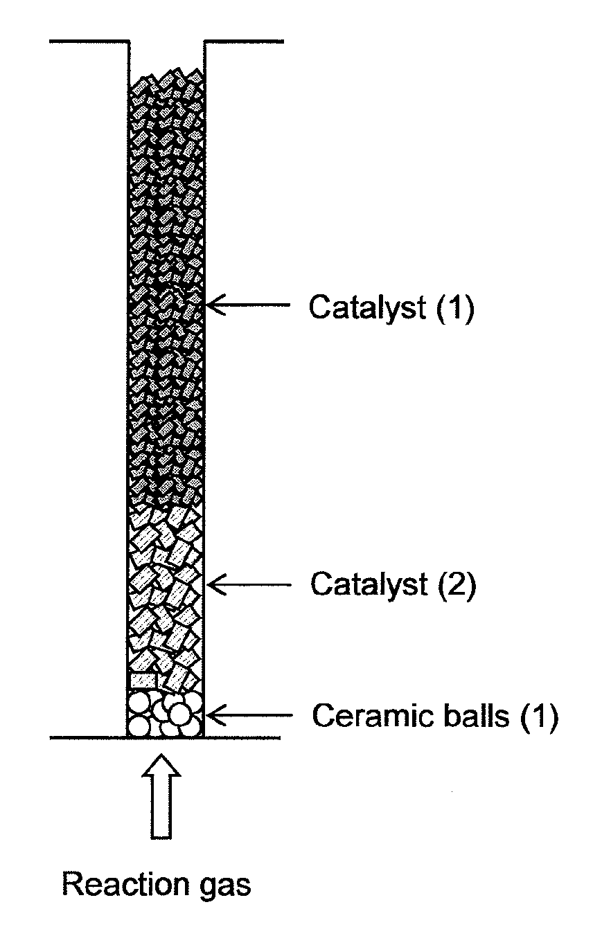
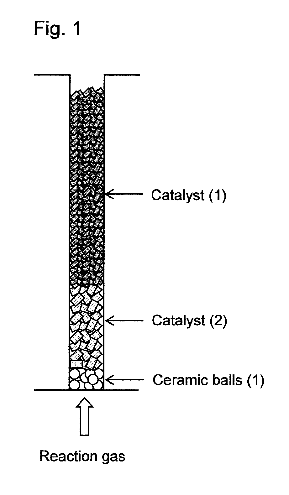
[0045]Into a fixed-bed multitubular reactor having 13,000 reaction tubes (reaction tube diameter: 25 mm, length: 3,500 mm) and a shell in which a heat medium is flowed and which covers the reaction tubes, ceramic balls having an average particle diameter of 8 mm, the catalyst (2), and the catalyst (1) were loaded, in this order from the bottom of the reaction tube, by dropping the respective solid particles from the tops of the reaction tubes so that the layer lengths comes to be 150 mm, 850 mm and 2,200 mm, respectively, as shown in FIG. 1. After loading each of the ceramic balls, the catalyst (2) and the catalyst (1), air of 20° C. was introduced from the tops of the reaction tubes at a linear velocity of 1.2 m / s and an introducing period of 12 seconds per reaction tube, whereby removal treatments of powdered particles generated during loading were performed. The removed powdered particles were captured by a bag filter installed to the bottoms of the reaction tubes. After the remo...


PUM

PropertyMeasurementUnit
linear velocityaaaaaaaaaa
lengthaaaaaaaaaa
humidityaaaaaaaaaa

Abstract

A method of loading solid particles into reaction tubes of a fixed-bed multitubular reactor, comprising the step of loading two or more kinds of solid particles into each of the reaction tubes so that the respective kinds of the solid particles are stacked in layers in a direction of an axis of the tube, wherein a gaseous fluid is introduced into the reaction tubes at least once every time the each kind of the solid particles is loaded in the layer.

Description

TECHNICAL FIELD[0001]The present invention relates to a method of loading solid particles such as a catalyst into a fixed-bed multitubular reactor.BACKGROUND ART[0002]As a method of loading solid particles such as a catalyst into a fixed-bed multitubular reactor, there is generally employed a method of dropping solid particles from an upper end opening of each reaction tube to load the particles into a reactor. In this method, however, a part of the solid particles may be disrupted or powdered due to physical impact upon dropping, and powdered particles resulting therefrom may increase a pressure loss or cause a substantive reduction of the amount of a catalyst to be engaged in a reaction. In addition, the powdered particles may cause a reduction of a yield of a target product or a catalyst lifetime. Moreover, the powdered particles may cause blockage of the reaction tubes due to by-products resulting from a nonuniform reaction in the reactor.[0003]As a way to solve these problems, ...

Claims


Application Information

Patent Timeline
Patent Type & Authority Applications(United States)
IPC IPC(8): B01J8/02C07C51/25
CPCB01J8/008B01J8/0292C07C51/252C07C51/00B01J2523/00B01J8/067B01J23/002B01J23/8885B01J35/0006B01J35/023B01J37/0009B01J2208/00752B01J2208/025C07C57/04B01J2523/17B01J2523/53B01J2523/55B01J2523/68B01J2523/69B01J2523/13B01J2523/54B01J2523/842B01J2523/845B01J2523/847
Inventor TANIMOTO, MICHIOHAKOZAKI, NOBUYUKIMIGITA, YUSAKU
Owner NIPPON SHOKUBAI CO LTD
Why Eureka
Try Eureka