Control valve for a ventilation system of an automobile

Inactive Publication Date: 2006-02-02
BEHR GMBH & CO KG
View PDF2 Cites 9 Cited by
  • Summary
  • Abstract
  • Description
  • Claims
  • Application Information

AI Technical Summary

Benefits of technology

[0006] The goal of this invention is to avoid and/or reduce known problems and to provide an improved control valve for ventilation systems, in particular in automobiles. The goal is achieved through a control valve as per the invention f

Problems solved by technology

The valves known from the state of the art exhibit, among other things, noise problems, for example, frequent hissing or whistling.
These noise problems occur in particular with small valve aperture angles of the control valve and are considered bothersome to automobile passengers.
The state of the art also uses different versions of flexible seals for control valves, which can lead to a noise problem depending on the application and the geometry of

Method used


Image

  • Control valve for a ventilation system of an automobile
  • Control valve for a ventilation system of an automobile
  • Control valve for a ventilation system of an automobile

Examples


Embodiment Construction

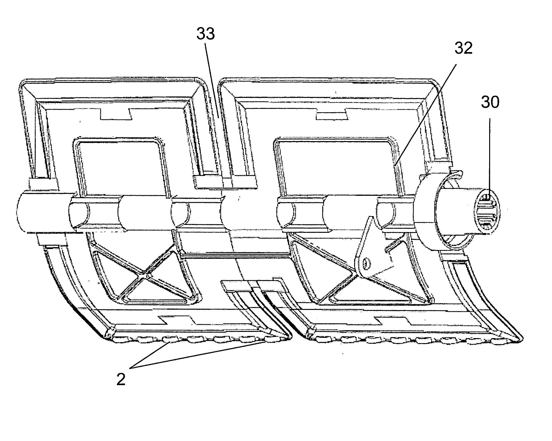
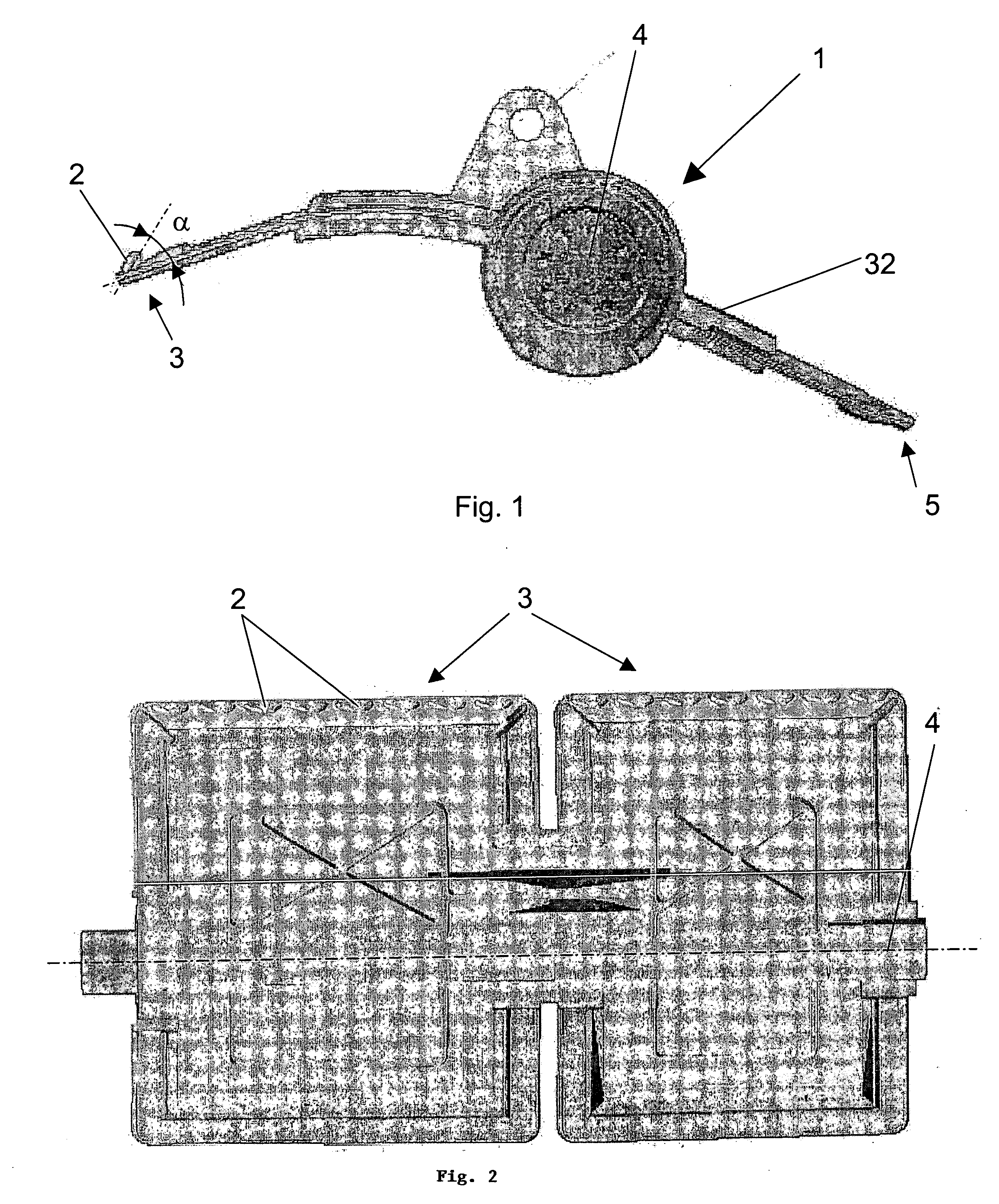
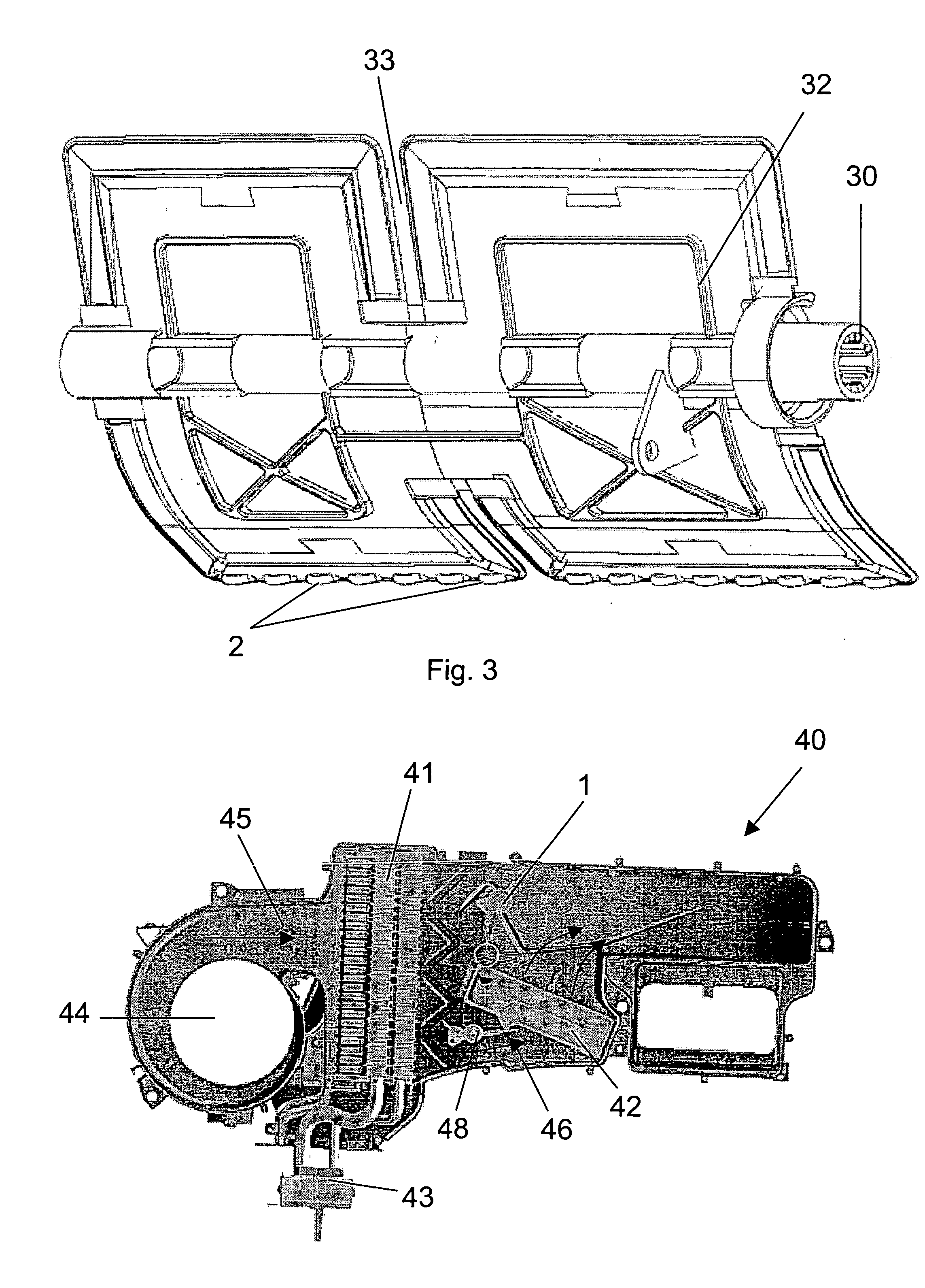
[0007] The valve as per the invention for a ventilation system of an automobile has at least one edge over which air passes and that can be moved at least from a first position to a second position. The control valve as per the invention is characterized in that the mainly two-dimensional valve, in particular in the area of the edge by which air passes, has a changing cross-sectional profil, which diverts at least a subarea of the passing air into a number of flow directions deviating from the main flow direction of the air flow.

[0008] As per this invention, the main direction is characterized as the direction of the main air flow, in which a number of flow particles mainly follow a predetermined flow path. The main flow direction can have a laminar flow, in particular in a subarea, which can however have turbulent areas, in particular in the edge areas, i.e. in the barrier layers.

[0009] In terms of this invention, the term “two-dimensional valve” is to be understood to mean the m...


PUM


Abstract

This invention concerns a control valve for a ventilation system of an automobile, with at least one edge over which air flows, which can be moved from at least a first into at least a second position. The control valve as per the invention is mainly two-dimensional and has in particular a changing cross-sectional profile in the area of the overflowed edge. Due to this cross-sectional profile, at least one sub area of the overflowing air is diverted into a number of flow directions deviating from the main flow direction.

Description

FIELD OF THE INVENTION [0001] This invention pertains to a control valve for a ventilation system of an automobile. BACKGROUND OF THE INVENTION [0002] Such control valves for a ventilation system of an automobile are known from the state of the art. These control valves are used, for example, in air ducts to change the volume flow but also to direct the air flow in a predetermined direction when there are a number of flow paths. Furthermore, such control valves also serve to open or close predetermined flow paths, e.g. for air, whereby, as is common for ventilation systems in automobiles, the air flow is directed, for example, to the foot area of the passengers or to the inside of the windshield. Certain components of the ventilation system can also be turned on by selecting the flow path. [0003] The valves known from the state of the art exhibit, among other things, noise problems, for example, frequent hissing or whistling. These noise problems occur in particular with small valve...

Claims


Application Information

Patent Timeline
IPC IPC(8): B60H1/00F24F13/14
CPCB60H2001/00721B60H1/00664
Inventor BURR, REINHOLDFRITSCHE, UWE
Owner BEHR GMBH & CO KG
Why Eureka
Try Eureka