Ventilator

a technology of ventilator and duct, which is applied in the field of ventilator, can solve the problems of flow noise generation and propagation, and achieve the effect of remarkably reducing the flow noise that is propagated from the du

Inactive Publication Date: 2007-03-01
LG ELECTRONICS INC
View PDF7 Cites 11 Cited by
  • Summary
  • Abstract
  • Description
  • Claims
  • Application Information

AI Technical Summary

Benefits of technology

[0010] An object of the present invention is to provide a ventilator that can minimize flow noise that propagates to the inside of a room through the duct by providing a sound-absorbing material that can absorb flow noise in a bent part of the duct when at least one bent part is formed at one side of the inside of a duct that guides the flow of suction air and exhaust gas.
[0031] According to a ventilator of the present invention having the above-mentioned construction, in a case where a duct for guiding the suction or exhaust flow has at least one bent part, flow noise is serious due to flow collision in the bent part of the duct. However, because a sound-absorbing material is provided in the bent part of the duct, flow noise that is propagated from the duct can be remarkably reduced.

Problems solved by technology

However, as described above, in the conventional ventilator, there is a problem in that flow noise is generated due to flow resistance in a duct that guides the flow of suction air or exhaust gas and the flow noise is propagated to the inside of the room through the duct.

Method used


Image

  • Ventilator
  • Ventilator
  • Ventilator

Examples


Embodiment Construction

[0039] Hereinafter, exemplary embodiments of a ventilator according to the present invention will be described in detail with reference to the accompanying drawings.

[0040] As those skilled in the art would realize, the described embodiments may be modified in various different ways, all without departing from the spirit or scope of the present invention. Now, the most preferred embodiment will be described.

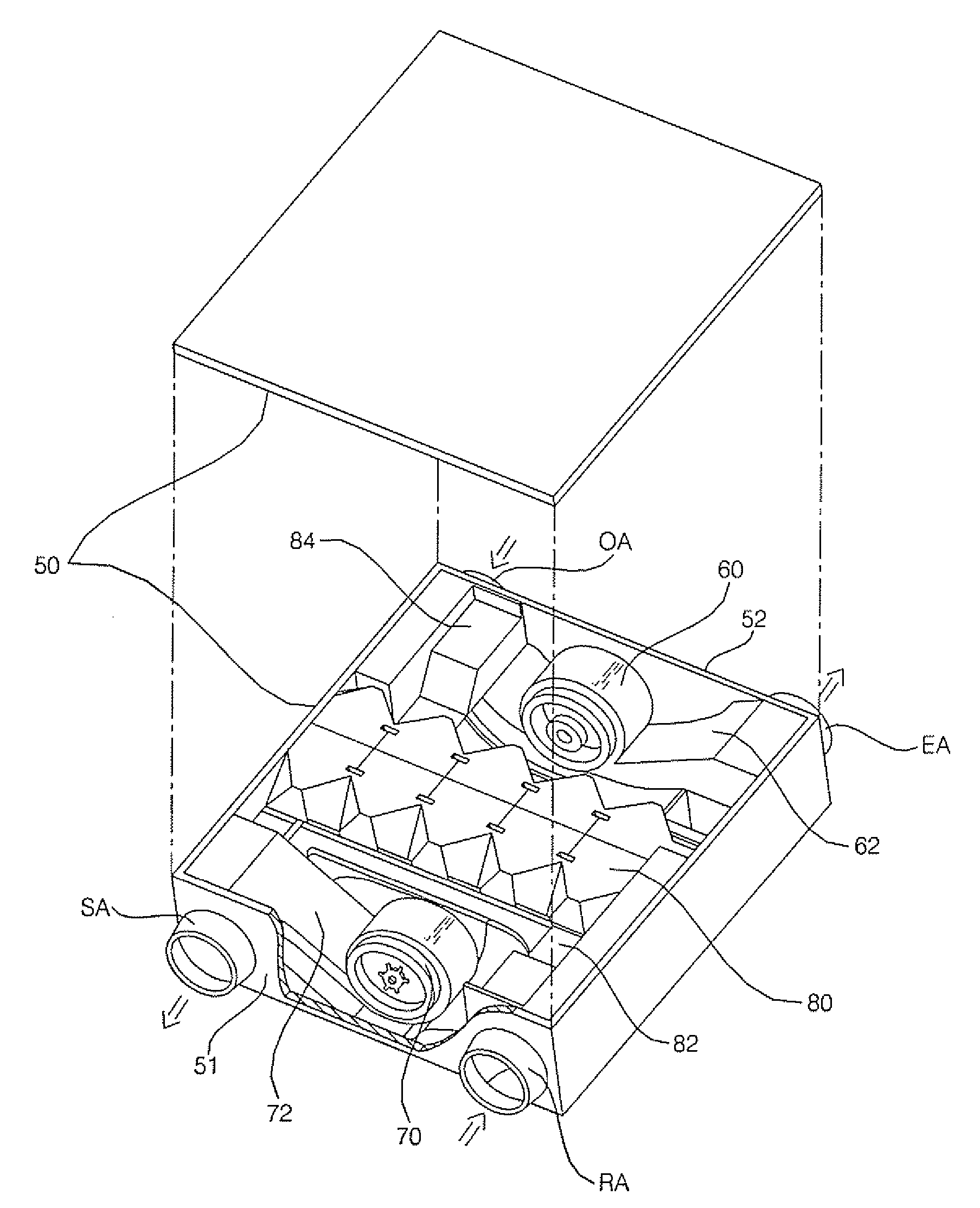
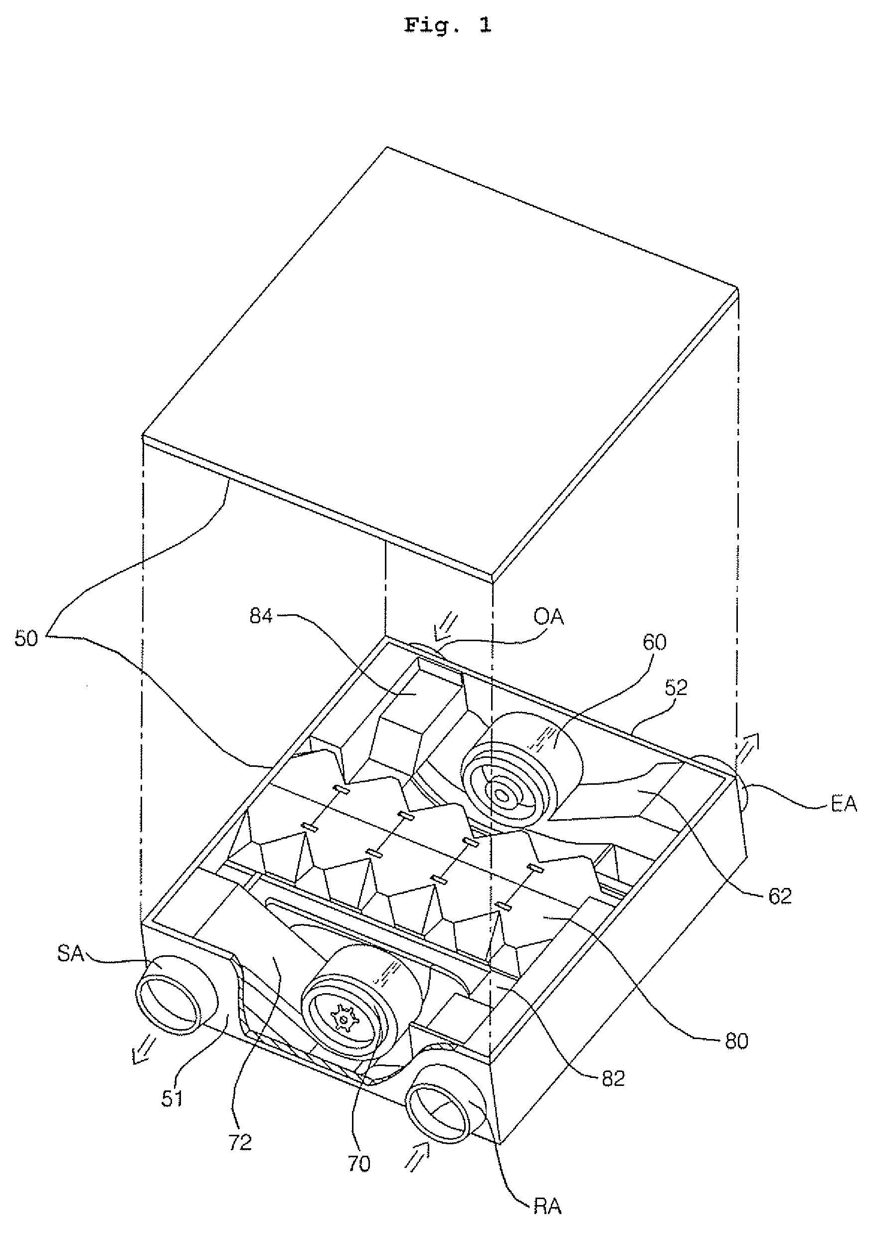
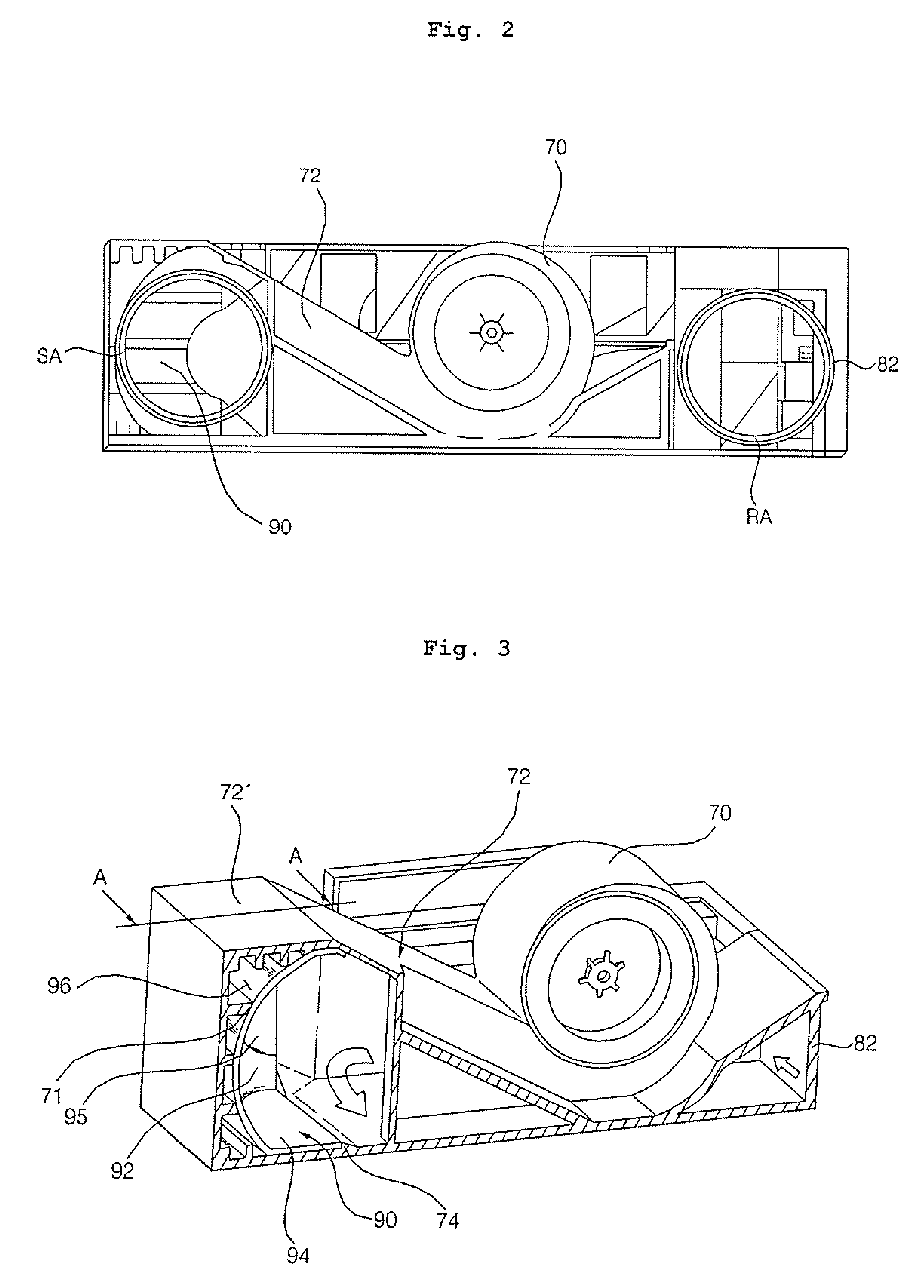
[0041]FIG. 1 is an exploded perspective view of a ventilator according to an embodiment of the present invention. FIG. 2 is a front view of a sound absorption structure of the ventilator according to an embodiment of the present invention. FIG. 3 is a perspective view of a sound absorption structure of the ventilator according to an embodiment of the present invention. FIG. 4 is an exploded perspective view of a sound absorption structure of the ventilator according to an embodiment of the present invention. FIG. 5 is a cross-sectional view of the sound absorption structure take...


PUM


Abstract

A ventilator is provided. The ventilator includes blowers 60 and 70; ducts 62 and 72 that are connected to the blowers 60 and 70 to form a blow path having at least one bent part; and a sound-absorbing material 90 that is provided in the bent part of the blow path of the ducts 62 and 72 to absorb noise within the blow path thereof. Therefore, it is possible to remarkably reduce or prevent flow noise that is propagated to the inside of a room as noise of a flow passing through the ducts 62 and 72 is absorbed by the sound-absorbing material 90.

Description

[0001] This Nonprovisional application claims priority under 35 U.S.C. §119(a) on Patent Application No. 10-2005-0073911 filed in Korea on Aug. 11, 2005, the entire contents of which are hereby incorporated by reference. BACKGROUND OF THE INVENTION [0002] 1. Field of the Invention [0003] The present invention relates to a ventilator, and more particularly, to a ventilator with a sound-absorbing material that can absorb flow noise within a duct that guides blowing power of a blower. [0004] 2. Description of the Background Art [0005] In general, a ventilator is an apparatus for exhausting contaminated indoor air to the outside of a room and for sucking fresh outdoor air to the inside of the room while maintaining a room temperature. [0006] As disclosed in Japanese Patent Application Laid-open No. 1999-287492 (Oct. 12, 1999), a conventional ventilator exhausts contaminated indoor air to the outside of a room via an exhaust blower and a heat exchanger with blowing power of the exhaust b...

Claims


Application Information

Patent Timeline
Patent Type & Authority Applications(United States)
IPC IPC(8): E06B7/02
CPCF24F13/24F24F7/007F24F7/08F24F13/0236
Inventor LEE, HO BEOMKIM, KYUNG HWANCHOI, KEUN HYOUNGCHOI, DONG WHANCHOI, HO SEONPARK, JONG HOONSONG, CHANG HYUN
Owner LG ELECTRONICS INC
Why Eureka
Try Eureka