
Display with integrated touch sensor and driving method thereof

a technology of integrated touch sensor and driving method, which is applied in the direction of instruments, computing, electric digital data processing, etc., can solve the problems of reducing the sensitivity and touch recognition rate of the touch sensor and the touch recognition rate, and achieve the effect of reducing the noise applied

Active Publication Date: 2012-09-27
LG DISPLAY CO LTD
View PDF7 Cites 114 Cited by
  • Summary
  • Abstract
  • Description
  • Claims
  • Application Information

AI Technical Summary

Benefits of technology

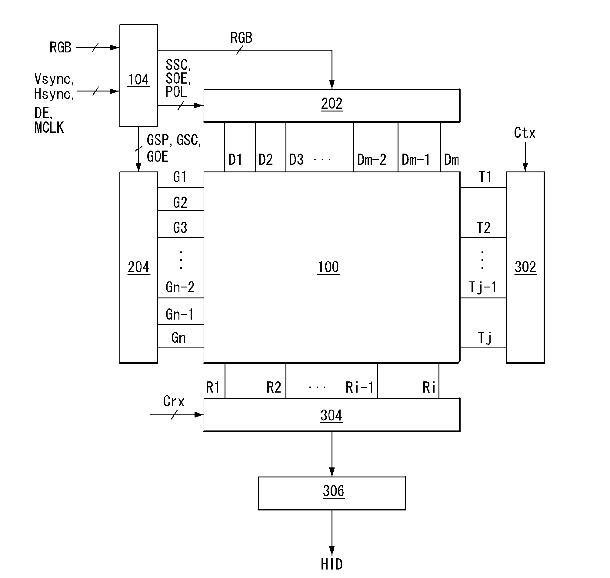
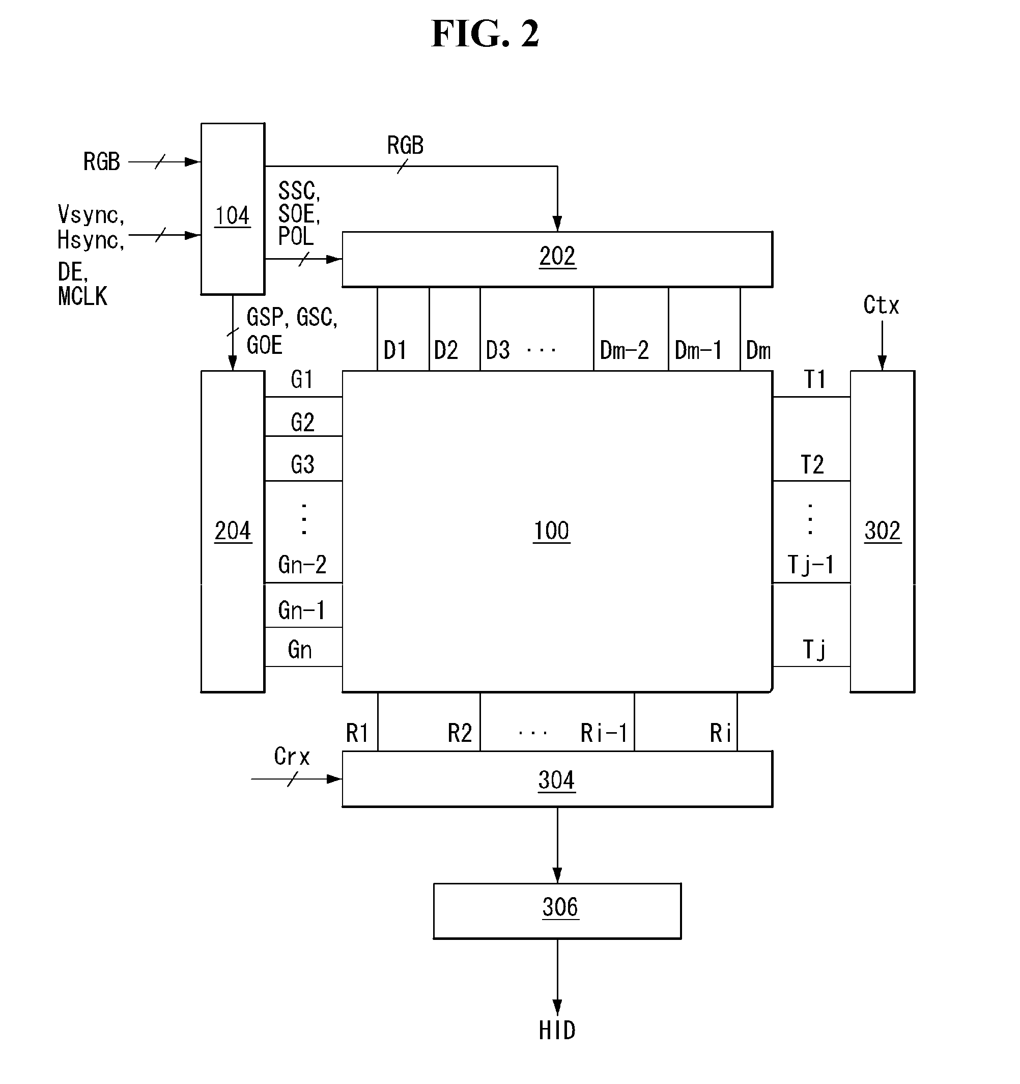
This patent describes a display with a built-in touch sensor that reduces interference from signal lines connected to pixels of the display. The display includes a display panel with data lines, gate lines, and Tx and Rx lines that cross each other and have mutual capacitances. A display data driving circuit supplies analog video data voltages to the data lines during both the display and touch sensor driving periods, while a display scan driving circuit sequentially supplies scan pulses to the gate lines during the display period. A touch sensor driving circuit sequentially supplies driving pulses to the Tx lines during the touch sensor driving period. A touch sensor readout circuit receives a touch signal from the mutual capacitances during the touch sensor driving period. The specific DC voltage is a ground voltage or a similar DC voltage. The method also includes sequentially supplying scan pulses and driving pulses to the Tx lines during the touch sensor driving period. The technical effect is that the display with integrated touch sensor has reduced interference from signal lines connected to pixels, resulting in improved touch sensing accuracy.

Problems solved by technology

This voltage is a noise component, which may reduce the sensitivity and touch recognition rate of the touch sensors and the touch recognition rate.

Method used


Image

  • Display with integrated touch sensor and driving method thereof
  • Display with integrated touch sensor and driving method thereof
  • Display with integrated touch sensor and driving method thereof

Examples


Embodiment Construction

[0025]Hereinafter, an implementation of this document will be described in detail with reference to the attached drawings. Throughout the specification, like reference numerals denote substantially like components. Hereinafter, the detailed description of related known functions or configurations that may unnecessarily obscure the subject matter of the present invention in describing the present invention will be omitted.

[0026]The display with integrated touch sensor of the present invention may be implemented as a flat panel display device, such as a liquid crystal display (LCD), a field emission display (FED), a plasma display panel (PDP), an organic light emitting display (OLED), or an electrophoresis (EPD), and touch sensors integrated in an in-cell type in the display panel of the flat panel display device. In an exemplary embodiment that follows, it should be noted that, although a liquid crystal display device will be described as an example of the flat panel display device, ...


PUM


Abstract

A display with integrated touch sensor and a driving method thereof are provided. The display comprises a display data driving circuit that supplies analog video data voltages to data lines of a display panel during a display period and maintains the voltage of the data lines at the same specific DC voltage during a touch sensor driving period; a display scan driving circuit that sequentially supplies scan pulses synchronized with the analog video data voltages to the gate lines of the display panel during the display period; a touch sensor driving circuit that sequentially supplies driving pulses to the Tx lines of the display panel during the touch sensor driving period; and a touch sensor readout circuit that receives a touch signal from the mutual capacitances via the Rx lines of the display panel during the touch sensor driving period.

Description

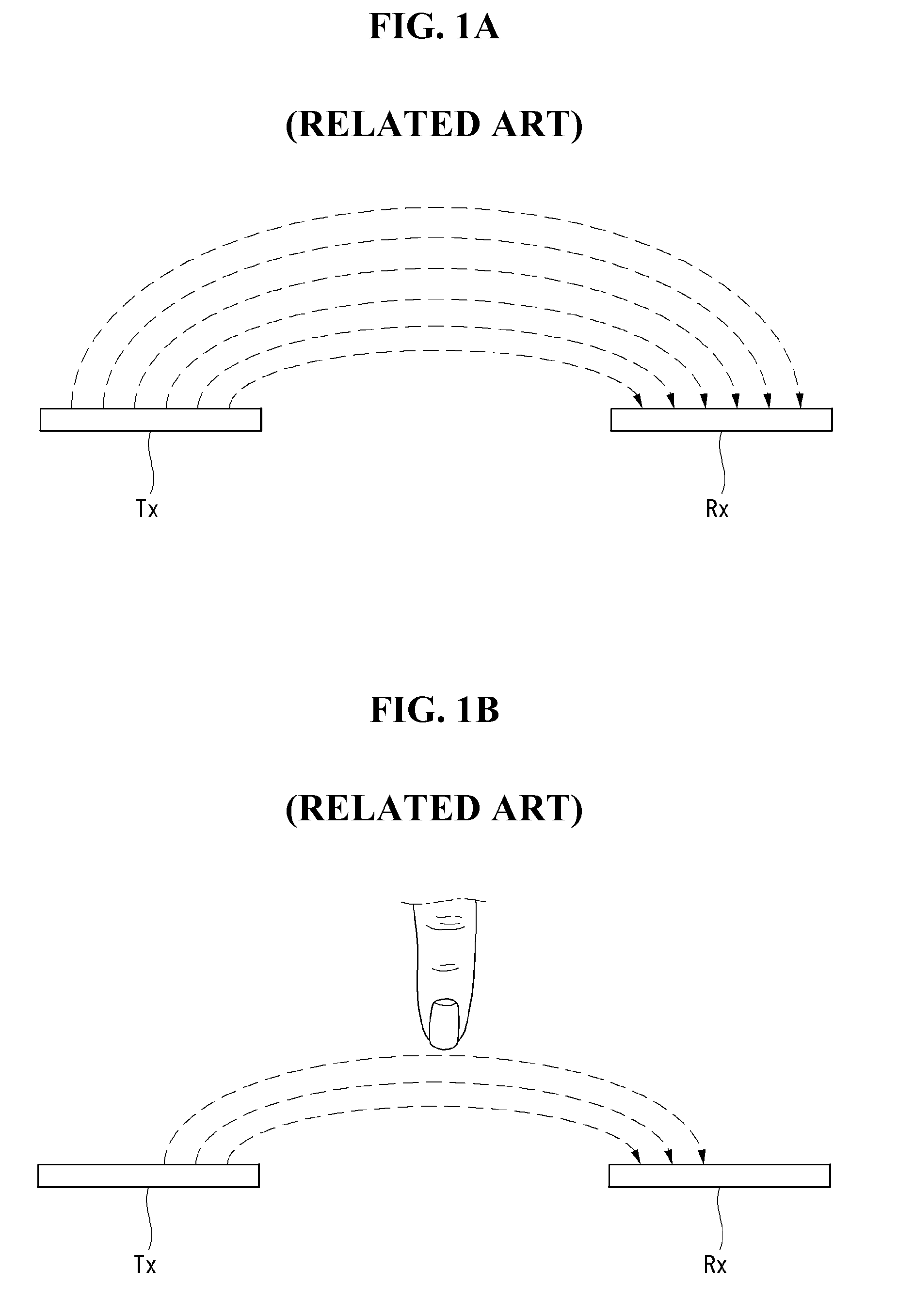
[0001]This application claims the benefit of Korea Patent Application No. 10-2011-0026915 field on Mar. 25, 2011, the entire contents of which is incorporated herein by reference for all purposes as if fully set forth herein.BACKGROUND[0002]1. Field[0003]This document relates to a display with integrated touch sensor and a driving method thereof.[0004]2. Related Art[0005]With a recent trend toward thin profile and lightness in weight of electric home appliances or personal digital appliances, a button switch as user's input means has been substituted for a touch sensor. A touch screen applied in a display device comprises a plurality of touch sensors. The touch sensors may be integrated in an in-cell type within the display panel.[0006]Capacitance type touch sensors can be implemented in a mutual capacitance type. The capacitance type touch sensors comprise mutual capacitance formed at intersections between signal lines Tx and Rx crossing each other as shown in FIG. 1a. When a finge...

Claims


Application Information

Patent Timeline
Patent Type & Authority Applications(United States)
IPC IPC(8): G06F3/041
CPCG06F3/0412G06F3/0418G09G2354/00G09G3/3648G06F3/044G06F3/0446G06F2203/04103G06F2203/04111G06F3/04166
Inventor HWANG, SANGSOOKIM, CHEOLSEHAN, MANHYEOP
Owner LG DISPLAY CO LTD
Learn More