All-fiber chirped pulse amplification systems

a chirped pulse amplification and all-fiber technology, applied in the field of ultracompact high-energy fiber pulse source construction, can solve the problems of requiring a significantly larger amount of space for their operation, the use of bulk stretchers and compressors is generally much more difficult to align, etc., and achieves the effect of greatly enhancing the performance of ‘conventional’ chirped pulse amplification systems and high utility

Inactive Publication Date: 2005-05-19
IMRA AMERICA
View PDF7 Cites 119 Cited by
  • Summary
  • Abstract
  • Description
  • Claims
  • Application Information

AI Technical Summary

Benefits of technology

[0019] Fiber-based high energy chirped pulse amplification systems of high utility can also be constructed from conventional optical components such as pulse stretchers based on long lengths of conventional fiber as well as bulk grating compressors. The performance of such ‘conventional’ chirped pulse amplification systems can be greatly enhanced by exploiting nonlinear cubicon pulse formation, i.e. by minimization of higher-order dispersion via control of self-phase modulation inside the amplifiers.
[0020] Finally, a particularly compact seed source for an Yb fiber-based chirped pulse amplification system can be constructed from an anti-Stokes frequency shifted modelocked Er fiber laser amplifier system, where a wavelength tunable output is obtained by filtering of the anti-Stokes frequency shifted output. The noise of such an anti-Stokes frequency shifted source is minimized by the amplification of positively chirped pulses in a negative dispersion fiber amplifier.

Problems solved by technology

Alternative arrangements resorting to the use of bulk stretchers and compressors (as generally used in the state of the art) are generally much more difficult to align, require a significantly larger amount of space for their operation and are only of limited utility in real industrial applications.
Therefore, the delivery of an optimally short optical pulse onto a target material by simply substituting a holey fiber with a photonic crystal fiber is not generally possible.
Moreover, because of the negligible values of first and second order polarization mode dispersion in typical non-polarization maintaining fiber amplifiers, U.S. Pat. No. 5,303,314 did not consider the use of Faraday rotators for the compensation of second-order polarization mode dispersion.
However, M. E. Fermann et al. did not suggest any independent control of second and third-order dispersion with such an amplitude filter.
Moreover, Fermann et al., did not suggest the use of a nonlinear amplifier for higher-order dispersion compensation in the presence of gain-narrowing and gain-pulling in the fiber amplifier.
However, Richardson et al. did not suggest controlling the third-order dispersion in such fiber amplifiers.
Moreover, U.S. Pat. No. 6,618,531 does not address stability issues for an anti-Stokes frequency shifted fiber laser.
Although anti-Stokes frequency shifting may produce a certain desired output wavelength, generally, such a source may not comply with the stability requirements of commercial laser sources.

Method used


Image

  • All-fiber chirped pulse amplification systems
  • All-fiber chirped pulse amplification systems
  • All-fiber chirped pulse amplification systems

Examples


Embodiment Construction

[0040] A detailed description of the preferred embodiments of the invention will now be given referring to the accompanying drawings.

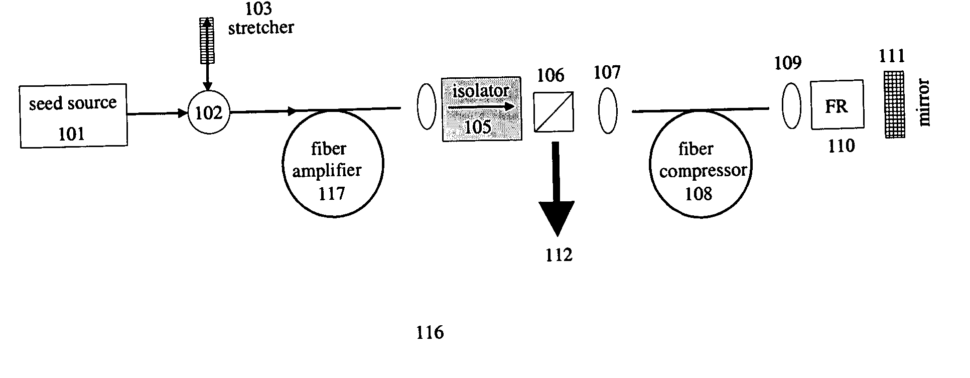
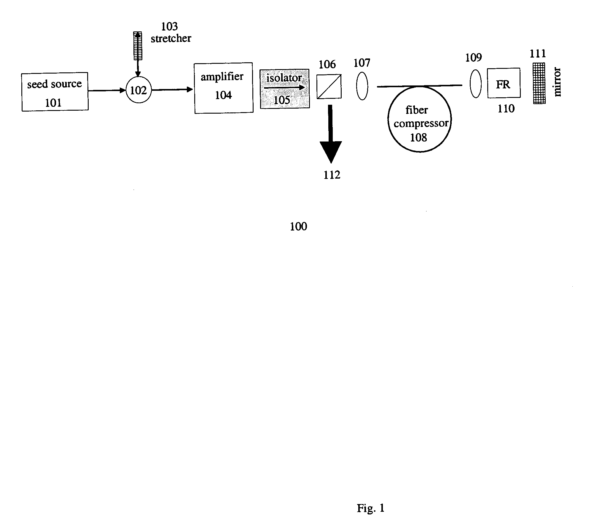
[0041]FIG. 1 represents an exemplary embodiment of a chirped pulse amplification system 100 according to the present invention. The system comprises a short pulse seed source 101. The seed source 101 generally supplies pulses having a width less than 50 picosecond. The pulses from seed source 101 are injected into an optical circulator 102 and a fiber Bragg grating stretcher 103 temporally stretches the pulses by at least a factor of ten. All-fiber circulators or bulk optic equivalents of optical circulators can be implemented. U.S. patent application Ser. No. 10 / 608,233, which is incorporated by reference for all it discloses, discusses such circulators, which will not be further described. The stretched pulses are then directed via the circulator output to an optical amplifier system 104. The optical amplifier system 104 can comprise a bulk-optic mu...


PUM


Abstract

By compensating polarization mode-dispersion as well chromatic dispersion in photonic crystal fiber pulse compressors, high pulse energies can be obtained from all-fiber chirped pulse amplification systems. By inducing third-order dispersion in fiber amplifiers via self-phase modulation, the third-order chromatic dispersion from bulk grating pulse compressors can be compensated and the pulse quality of hybrid fiber/bulk chirped pulse amplification systems can be improved. Finally, by amplifying positively chirped pulses in negative dispersion fiber amplifiers, low noise wavelength tunable seed source via anti-Stokes frequency shifting can be obtained.

Description

CROSS-REFERENCES TO RELATED APPLICATIONS [0001] This is a Continuation-In-Part of U.S. application Ser. No. 10 / 608,233 filed on Jun. 30, 2003, the entire disclosure of which is hereby incorporated by reference. This application claims benefit of the filing date of the Provisional Application Ser. No. 60 / 539,110 filed on Jan. 27, 2004. The Provisional Application Ser. No. 60 / 539,110 is incorporated herein by reference for all it discloses.TECHNICAL FIELD OF THE INVENTION [0002] The present invention is direct to the construction of ultra-compact high-energy fiber pulse sources. DESCRIPTION OF RELATED ART [0003] Over the last several years, fiber lasers and amplifiers have been regarded as the most promising candidates for ultrafast pulse sources for advanced industrial applications due to their unique simplicity of construction. In general, ultrafast optical pulses have a pulse width of less than 50 picoseconds. Chirped pulse amplification is implemented to enable the amplification o...

Claims


Application Information

Patent Timeline
Patent Type & Authority Applications(United States)
IPC IPC(8): G02B6/26H01S3/00H01S3/067
CPCH01S3/0057H01S3/1301H01S3/0078H01S3/06712H01S3/06725H01S3/06741H01S3/06754H01S3/06758H01S3/094007H01S3/1086H01S3/1608H01S3/1618H01S3/2308H01S3/2316H01S3/302H01S3/0064H01S3/00
Inventor FERMANN, MARTIN E.IMESHEV, GENNADYCHO, GYU C.LIU, ZHENLINHARTER, DONALD J.
Owner IMRA AMERICA
Why Eureka
Try Eureka