Catalytic hydrogenation process utilizing multi-stage ebullated bed reactors

Inactive Publication Date: 2001-08-07
IFP NORTH AMERICA
View PDF9 Cites 241 Cited by
  • Summary
  • Abstract
  • Description
  • Claims
  • Application Information

AI Technical Summary

Benefits of technology

FIG. 4 is a graph generally showing the effect of reactor gas hold-up volume percen

Problems solved by technology

Utilizing such external gas/liquid separation results in an increased volume of particulate catalyst being provided in a particular size reactor and

Method used


Image

  • Catalytic hydrogenation process utilizing multi-stage ebullated bed reactors
  • Catalytic hydrogenation process utilizing multi-stage ebullated bed reactors
  • Catalytic hydrogenation process utilizing multi-stage ebullated bed reactors

Examples


Example

EXAMPLE

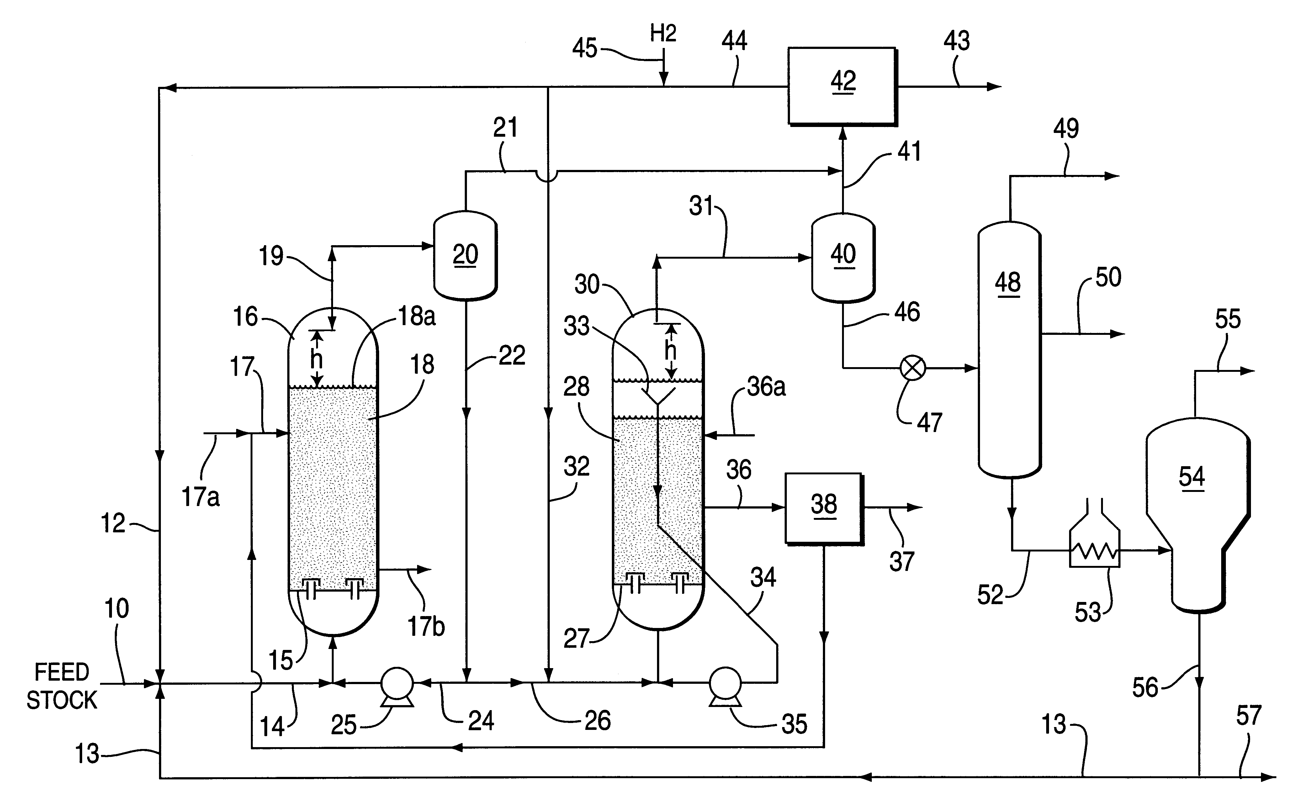
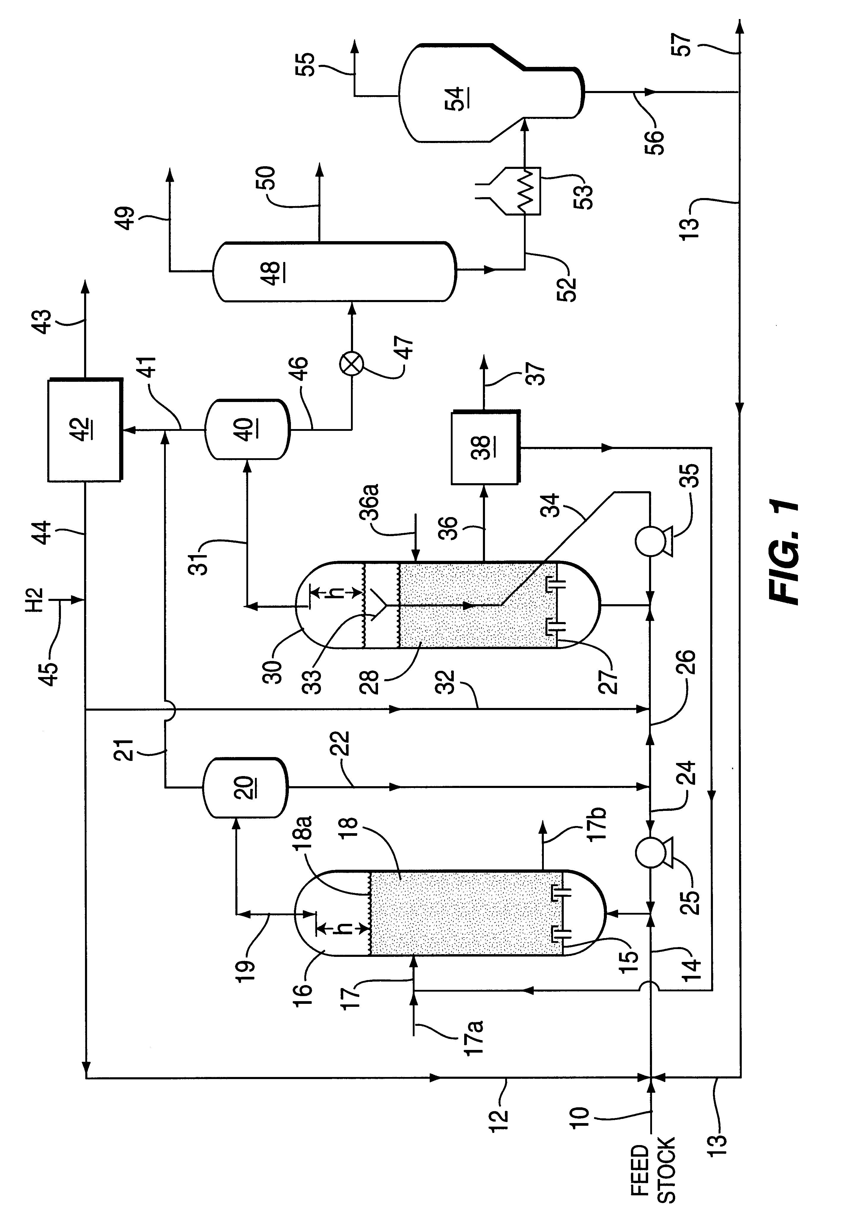
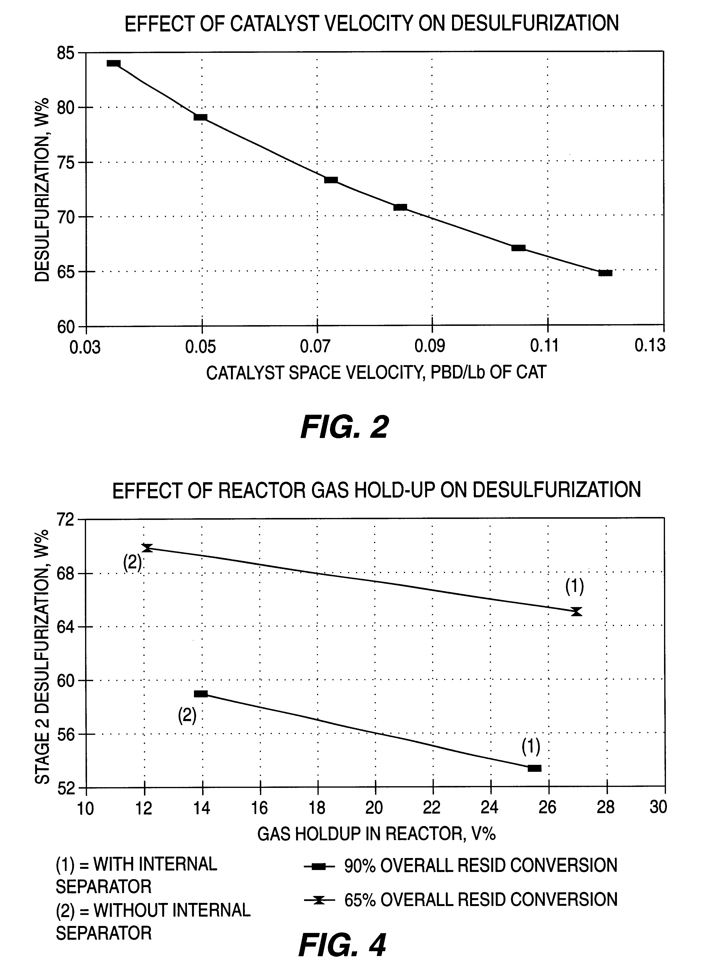
To demonstrate the process advantages of this invention, analyses of four commercial ebullated-bed reactor cases have been developed and are presented below. The basis for these comparative cases is the catalytic two-stage ebullated bed reactor processing of a typical Arabian light / heavy vacuum resid feedstock and providing 65 and 90 vol. % hydroconversion of the 1050.degree. F..sup.+ vacuum residua fraction and with a high percentage level of desulfurization. The vacuum residua feedstock has inspection analyses as shown in Table 3 below.

Two conventional process base cases No. 1 and 3 which do not incorporate features of the present invention and two improvement cases No. 2 and 4 which do incorporate features of this invention have been developed, and show clearly the process performance advantages of the invention. The cases No. 1 and 2 comparisons are both for a moderate 65 vol. % overall hydroconversion of the 1050.degree. F..sup.+ vacuum residua fraction, and the cases No...


PUM


Abstract

A process for catalytic multi-stage hydrogenation of heavy carbonaceous feedstocks using catalytic ebullated bed reactors is operated at selected flow and operating conditions so as to provide improved reactor operations and produce increased yield of lower boiling hydrocarbon liquid and gas products. The disclosed process advantageously takes advantage of an external gas/liquid separation unit associated with the first stage reactor to allow for a more efficient and effective catalytic hydrocracking process. The more efficient process is primarily a result of the increased catalyst loading and lower gas hold-up in the ebullated reactors.

Description

BACKGROUND OF INVENTIONThis invention pertains to improved catalytic hydrogenation of heavy hydrocarbonaceous feedstocks utilizing catalytic multi-stage ebullated bed reactors for producing desired lower boiling hydrocarbon liquid products. It pertains particularly to such catalytic multi-stage hydrogenation processes having increased catalyst loading and liquid volume together with reduced gas hold-up in each reactor, and thereby provides improved performance efficiency for the processes.In conventional catalytic hydrogenation processes for heavy hydrocarbon feedstocks utilizing multi-stage ebullated bed reactors, the hydrogen gas recycle rate in each reactor is usually kept relatively high to assure that excess hydrogen gas exists in the catalyst bed to provide the necessary chemical hydrogenation reactions with the feedstock. However, such excess hydrogen flow requires relatively high superficial gas velocities in the reactor(s), which results in less available volume for the rea...

Claims


Application Information

Patent Timeline
IPC IPC(8): C10G65/10C10G65/00
CPCC10G65/10C10G47/26C10G2300/4081
Inventor COLYAR, JAMES J.MACARTHUR, JAMES B.PEER, ERIC D.
Owner IFP NORTH AMERICA
Why Eureka
Try Eureka