Electronic valve controlling method for air conditioner

A control method and electronic valve technology, which is applied in the field of electronic valve control of regulators, can solve problems such as user dissatisfaction, increased refrigerant volume, refrigerant flow noise, etc., and achieve the effects of improving satisfaction, reducing flow noise, and stable operation

Inactive Publication Date: 2007-01-03
LG ELECTRONICS (TIANJIN) APPLIANCES CO LTD
View PDF0 Cites 10 Cited by
  • Summary
  • Abstract
  • Description
  • Claims
  • Application Information

AI Technical Summary

Problems solved by technology

[0005] However, as mentioned above, when the compressor stops driving and expands the electronic valve, there is a pressure difference between the front end and the rear end of the electronic valve, so that the a

Method used


Image

  • Electronic valve controlling method for air conditioner
  • Electronic valve controlling method for air conditioner

Examples


Embodiment Construction

[0013] Specific embodiments of the present invention will be described in detail below with reference to the accompanying drawings, but the present invention is not limited to the embodiments described below, within the scope of the basic technical ideas of the present invention, those skilled in the relevant industries can easily deduce Other embodiments, other embodiments deduced above all fall within the scope of the claims of the present invention.

[0014] Meanwhile, in the following embodiments, a composite air conditioning system in which a single outdoor unit is connected to multiple indoor units is used as an example for illustration, but the basic technical idea of ​​the present invention is not limited thereto.

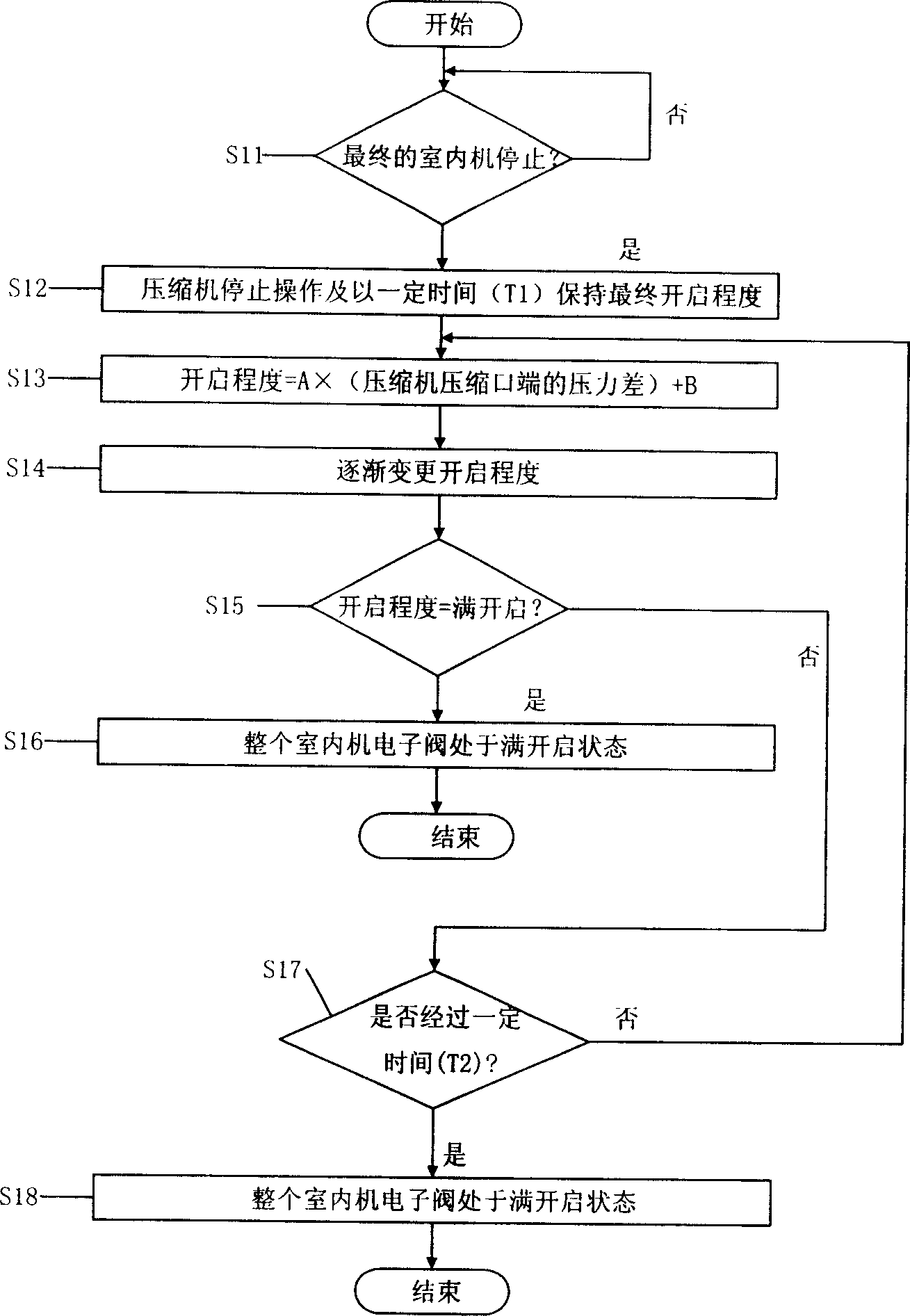
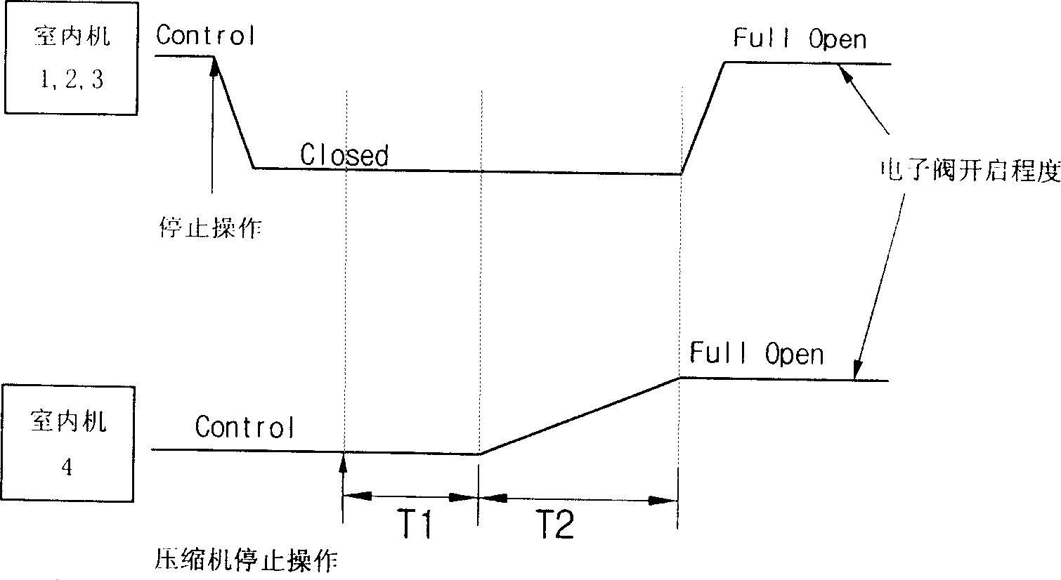
[0015] figure 1 It is a flowchart for explaining the electronic valve control method of the air conditioner in the present invention.

[0016] Refer to the above attached figure 1 , the electronic valve control method of the air conditioner in the present...


PUM


Abstract

This invention relates to electronic valve controlling method of air conditioner. It includes: steps for all the indoor machines stop working; steps for compressor stops working and after certain times, the opening degree of all electronic valves that connect to indoor machines reach full-opening degree. This invention can decrease refrigerants flowing noise of electronic valve after compressor stopping working.

Description

technical field [0001] The present invention relates to an electronic valve control method of an air conditioner, more specifically, it is an electronic valve control method for an air conditioner that reduces the flow noise caused by the refrigerant flowing in the electronic valve, thereby improving user satisfaction when using the air conditioner, and more specifically That is to say, in a multi air conditioner (multi air conditioner), when the compressor stops operating, the opening degree of the electronic valve is appropriately adjusted, thereby reducing the flow noise caused by the refrigerant flowing in the electronic valve. valve control method. Background technique [0002] A compound air conditioner in the general sense refers to a single outdoor unit connected to multiple indoor units, which can distribute and supply the refrigerant compressed by a compressor to the above-mentioned multiple indoor units, and perform air conditioning on each indoor space. . The t...

Claims


Application Information

Patent Timeline
IPC IPC(8): F24F11/00
Inventor 任成燁
Owner LG ELECTRONICS (TIANJIN) APPLIANCES CO LTD
Why Eureka
Try Eureka