De-Cel dampener method and apparatus

a dampener and decel technology, applied in the direction of shock absorbers, mechanical control devices, instruments, etc., can solve the problems of unwanted noise, wear, and inability to provide the driver with a low gear control setting, and achieve the effect of dampening the sound associated with the gear shi

Active Publication Date: 2009-09-15
KONGSBERG AUTOMOTIVE AS
View PDF3 Cites 13 Cited by
  • Summary
  • Abstract
  • Description
  • Claims
  • Application Information

AI Technical Summary

Benefits of technology

[0004]The foregoing needs are met, to a great extent, by a gear shift assembly comprising a frame member configured to be secured to a vehicle and having a plurality of gate structures defining a range of gear positions. A yoke is movably connected to the frame for movement through the range of gear positions. An actuation assembly is mounted to the yoke. The actuation assembly comprises an actuation member movable between a holding position and a releasing position and a detent structure movable between a gear holding position and a gear releasing position. The actuation member is operatively coupled to the detent structure so that movement of the actuation member from the holding position thereof to the releasing position thereof moves the detent structure from the gear holding position thereof to the gear releasing position thereof and movement of the actuation member from the releasing position thereof to the holding position thereof allows movement of the detent structure from the gear releasing position thereof into the gear holding position thereof. The frame member, the yoke and the detent structure are constructed and arranged such that when the detent structure is in the gear releasing position thereof the yoke is movable through the range of gear positions and such that when the detent structure is in the gear holding position thereof, the detent structure is engaged with one of the gate structures and the yoke is releasably held in a gear position with respect to the frame member. A dampening element is constructed of a resilient material and has a dampening surface positioned such that as the detent structure moves toward the gear holding position thereof, engagement of the detent structure with the dampening surface decelerates movement of the detent structure to dampen sound associated with the movement.
[0007]In some embodiments of the invention, a gear shift assembly comprises a frame member configured to be secured to a vehicle and has a plurality of gate structures defining a range of gear positions. A shifting mechanism is movably mounted within the frame for movement through the range of gear positions. The shifting mechanism comprises an actuation member movable between a holding position and a releasing position, and a detent structure movable between a gear holding position and a gear releasing position. The actuation member is operatively coupled to the detent structure so that movement of the actuation member from the locking position thereof to the releasing position thereof moves the detent structure from the gear holding position thereof to the gear releasing position thereof and movement of the actuation member from the releasing position to the holding position thereof allows movement of the detent structure from the gear releasing position into the gear holding position thereof. The frame member and the shifting mechanism is constructed and arranged such that when the detent structure is in the gear releasing position thereof the shifting mechanism is movable through the range of gear positions and such that when the detent structure is in the gear holding position thereof, the detent structure is engaged with one of the gate structures and the shifting mechanism is releasably held in a gear position with respect to the frame member. A dampening means is constructed and arranged such that as the detent structure moves toward the gear holding position thereof, engagement of the detent structure with the dampening means decelerates and stops movement of the detent structure to dampen sound associated with the movement.

Problems solved by technology

Some vehicle do not provide the driver with a low gear control setting.
Operation of the shift assembly may involve movement of vehicle components which can result in unwanted noise and wear on the components.

Method used


Image

  • De-Cel dampener method and apparatus
  • De-Cel dampener method and apparatus
  • De-Cel dampener method and apparatus

Examples


Embodiment Construction

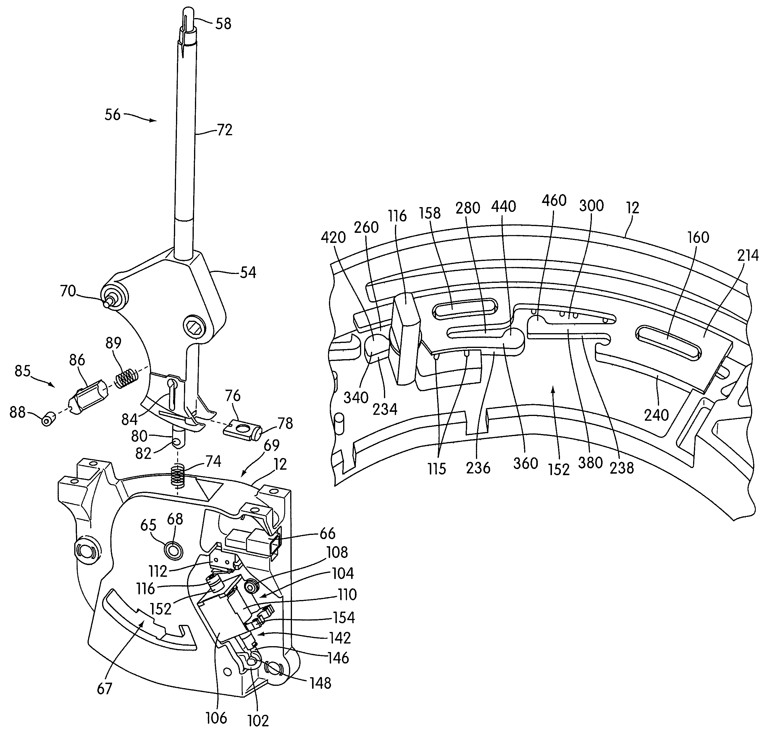
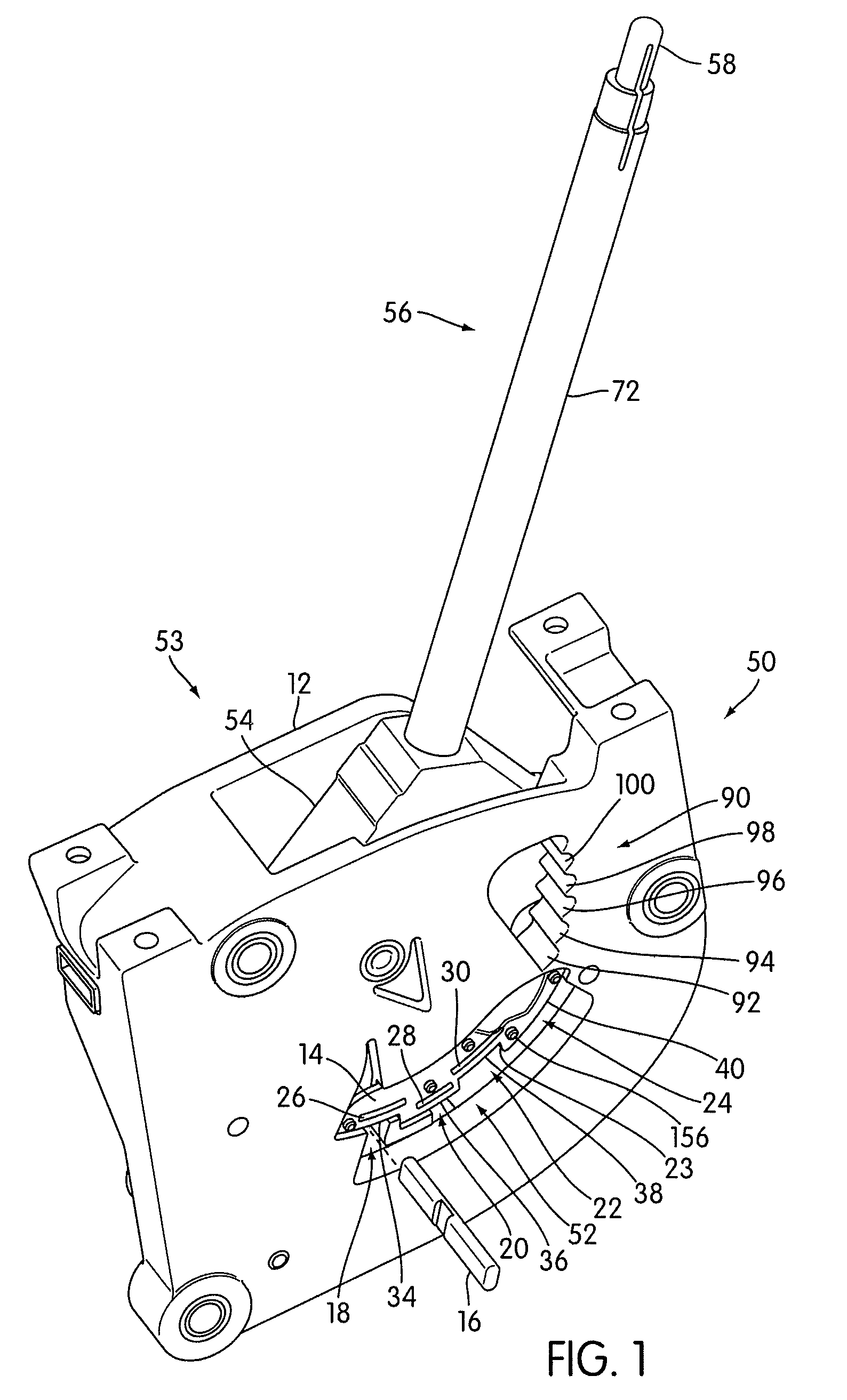
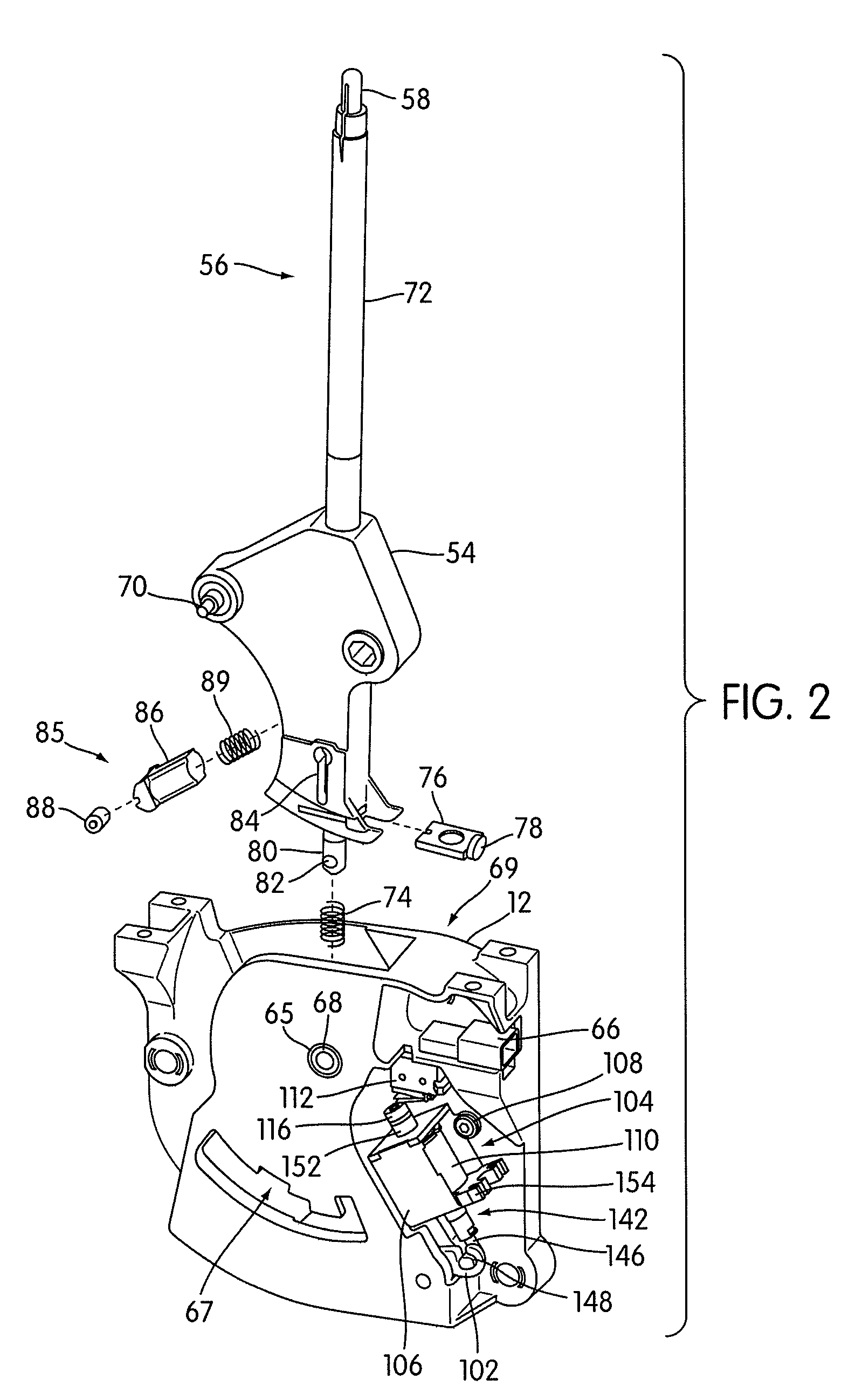
[0019]The invention will now be described with reference to the drawing figures, in which like numerals refer to like parts throughout. FIG. 1 shows an example of a gear shift assembly 50 constructed according to principles of the invention. Generally, the gear shift assembly 50 includes a frame member 12 configured to be secured to a vehicle and having a plurality of gate structures, generally designated 52. The gate structures 52 include gates 18, 20, 22, 24 which define a range of gear positions (shown in FIG. 6). The location of each gear position is indicated by an imaginary axis in FIG. 6. The gear positions include a park position P, a reverse position R, a neutral position N, a drive position D, and a three low gear positions L3, L2, L1. A yoke 54 is movably connected to the frame 12 for movement through the range of gear positions.

[0020]An actuation assembly 56 is mounted to the yoke 54. The actuation assembly 56 includes an actuation member 58 and a detent structure 16. Th...


PUM


Abstract

A motor vehicle gear shift assembly includes a dampening device and a detent structure. The dampening device includes a body structure made of a resilient material, a mounting structure for securing it to structure of the gear shift assembly, and a flexible dampening surface. The flexible dampening surface of the dampening device flexes to decelerate and stop the movement of the detent structure.

Description

CROSS-REFERENCE TO RELATED APPLICATIONS[0001]The present application is a non-provisional application of U.S. patent application Ser. No. 60 / 849,462 filed Oct. 5, 2006, the contents of which is incorporated herein by reference in its entirety.FIELD OF THE INVENTION[0002]The present invention relates generally to motor vehicles. More particularly, the present invention relates to motor vehicle gear shift assemblies.BACKGROUND OF THE INVENTION[0003]A motor vehicle often includes a gear shift assembly which enables a vehicle operator to control the transmission of the vehicle and to take the vehicle in and out of gear. The control positions provided by a gear shift assembly for a vehicle typically include park, reverse, neutral, drive, and low, which positions are often designated, respectively, by the letters P, R, N, D and L. The total number of gear shift positions may vary from vehicle to vehicle. In some vehicles there may be a range of low gears which are typically designated by ...

Claims


Application Information

Patent Timeline
Patent Type & Authority Patents(United States)
IPC IPC(8): B60K20/00
CPCF16H59/10F16H59/0208Y10T74/2011Y10T74/20018Y10T74/20116F16H61/24B60K20/02
Inventor GORMAN, PATRICKBORTOLON, CHRIS
Owner KONGSBERG AUTOMOTIVE AS
Why Eureka
Try Eureka