Circuit device
a circuit device and circuit technology, applied in the field of circuit devices, can solve the problems of low reliability, high demand for high function and high performance of lsis, and the product must be small and lightweight, so as to reduce the propagation of ground nois
- Summary
- Abstract
- Description
- Claims
- Application Information
AI Technical Summary
Benefits of technology
Problems solved by technology
Method used
Image
Examples
first embodiment
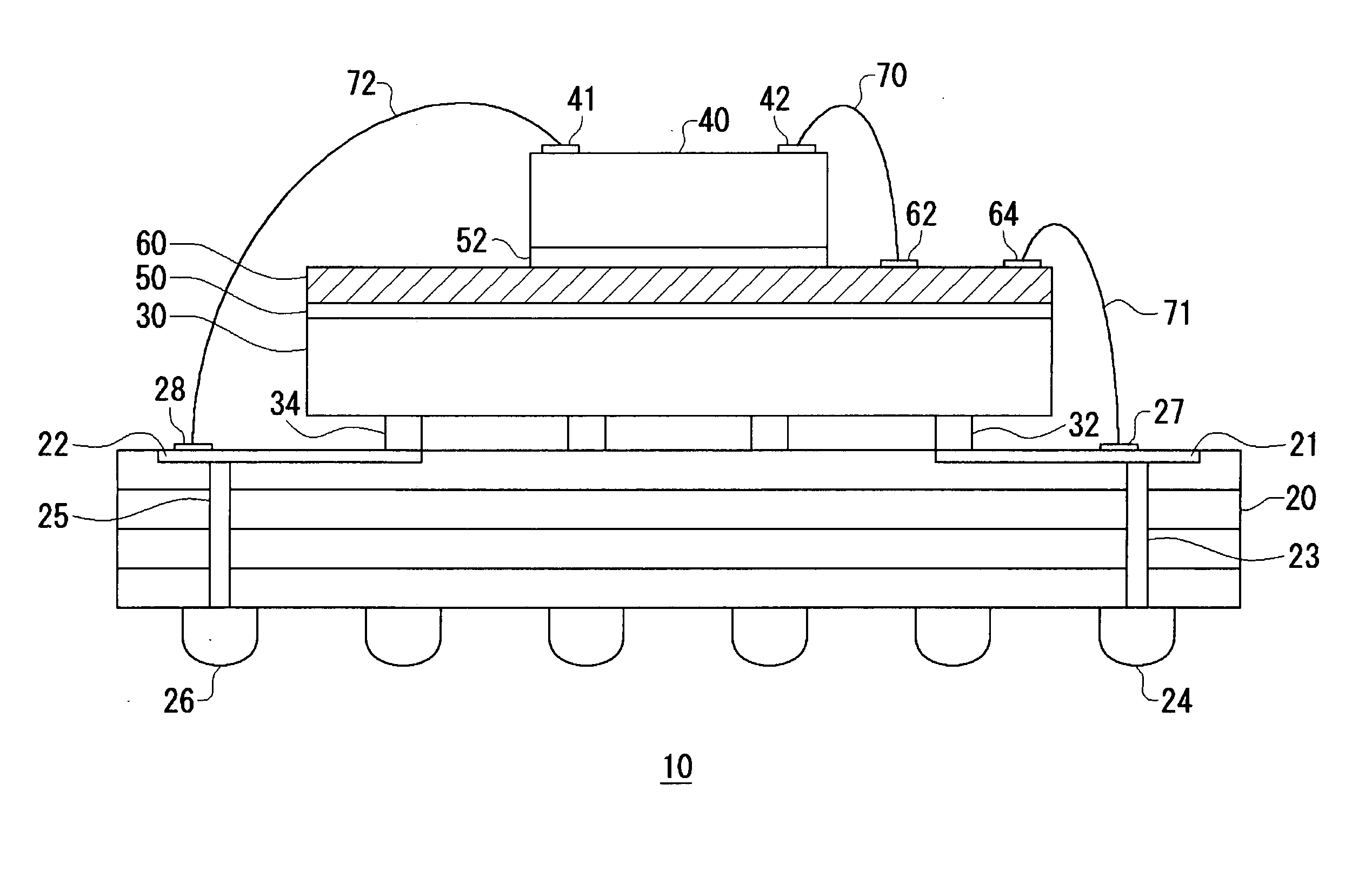
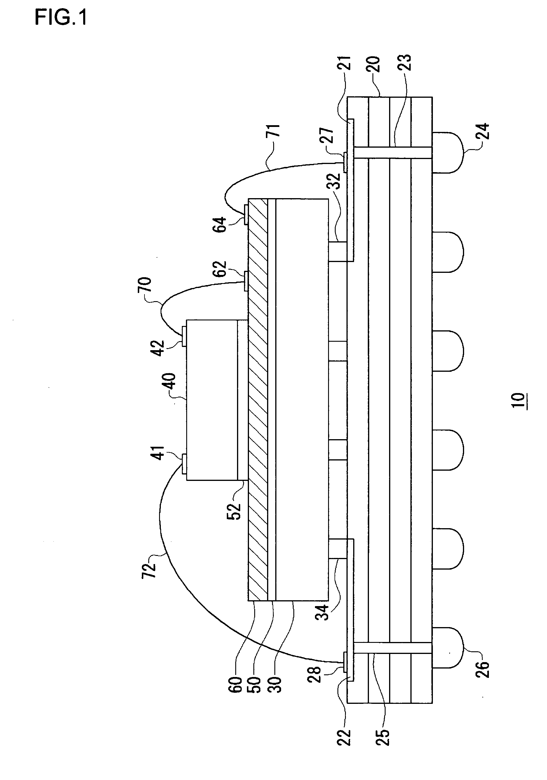
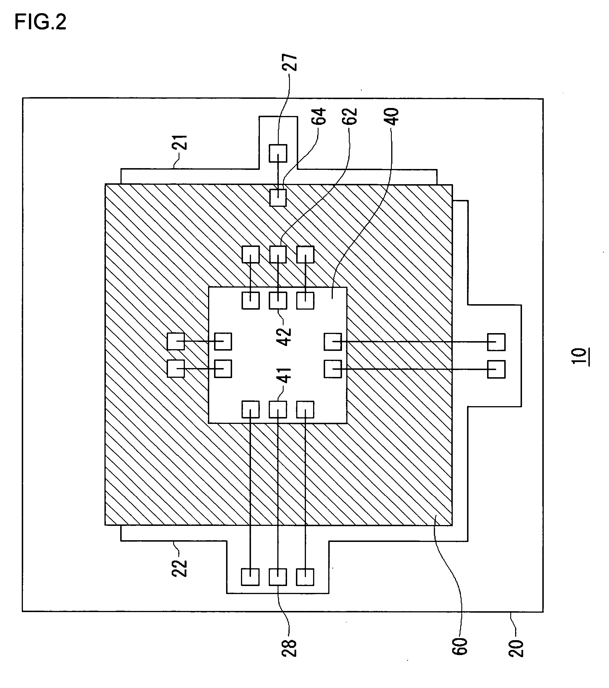
[0047]FIG. 1 is a cross-sectional view showing a structure of a circuit device according to a first embodiment of the present invention. FIG. 2 is a plan view showing a circuit device according to the first embodiment.
[0048] A circuit device 10 according to the first embodiment includes a substrate 20, a first circuit element 30, which is flip-chip-bonded to the substrate 20, a second circuit element 40, which is stacked on top of the first circuit element 30, a pair of insulation layers, namely, an insulation layer 50 and an insulation layer 52, which are interposed between the first circuit element 30 and the second circuit element 40, and a conductive layer 60, which is interposed between the insulation layer 50 and the insulation layer 52.
[0049] The substrate 20 has a multilayer wiring structure of a plurality of stacked wiring layers. Provided on the surface of the substrate 20 are a ground wiring 21 and a power supply wiring 22. The ground wiring 21 is connected to a BGA bal...
second embodiment
[0080]FIG. 6 is a cross-sectional view showing a structure of a circuit device 500 according to a second embodiment of the present invention. FIG. 7 is a plan view showing a circuit device according to the second embodiment.
[0081] A circuit device 500 according to the second embodiment differs from the circuit device 10 according to the first embodiment in that the circuit elements of the second embodiment are formed by three stacks. A description will be given here of the circuit device 500 according to the second embodiment centering around a structure different from that of the first embodiment.
[0082] According to the second embodiment, a third circuit element 580 is further laminated on the second circuit element 40. A pair of insulation layers 550 and 570 are provided between the third circuit element 580 and the second circuit element 40. A conductive layer 560 is interposed between the insulation layer 550 and the insulation layer 570.
[0083] A bonding pad 530, for power su...
third embodiment
[0086]FIG. 8 is a cross-sectional view showing a structure of a circuit device 600 according to a third embodiment of the present invention. A description will be given hereinbelow of the circuit device 600 according to the third of the first embodiment. A packaged second circuit element 40 is used in the circuit device 600. A first circuit element mounted on a substrate 20 and the packaged second circuit element 40 are further packaged.
[0087] A structure characteristic of the circuit device according to the third embodiment will now be described. A conductive layer 610 for power supply is formed on an insulation layer 50. A bonding pad 620 for power supply is formed on the surface of the conduction layer 610. The bonding pad 620 for power supply provided on the conductive layer 610 and a bonding pad 41 provided on the second circuit element 40 are electrically connected together via a power supply wire 62 made of gold or the like. The second circuit element 40 together with electr...
PUM
 Abstract
Description
Claims
Application Information
 - R&D
- Intellectual Property
- Life Sciences
- Materials
- Tech Scout
- Unparalleled Data Quality
- Higher Quality Content
- 60% Fewer Hallucinations
Browse by: Latest US Patents, China's latest patents, Technical Efficacy Thesaurus, Application Domain, Technology Topic, Popular Technical Reports.
© 2025 PatSnap. All rights reserved.Legal|Privacy policy|Modern Slavery Act Transparency Statement|Sitemap|About US| Contact US: help@patsnap.com


