Locking apparatus of truck with hoist

Inactive Publication Date: 2006-10-26
AONO CO LTD
View PDF9 Cites 5 Cited by
  • Summary
  • Abstract
  • Description
  • Claims
  • Application Information

AI Technical Summary

Benefits of technology

[0015] In accordance with the first aspect of the present invention, at an initial time when the parallel link mechanism is actuated to a downward movement side on the basis of a dead weight of the hoist table, the engagement arms of the locking apparatus are pressed frontward by the upper end portions of the link arms of the parallel link mechanism, the engagement bodies move to the front end side of the guide grooves after opening the check valves so as to pass through these portions, and the check valves are thereafter closed on the basis of a dead weight. When positioning the hoist table to the lower surface side of the box container in this state and stepping down (operating) the actuating lever so as to actuate the parallel link mechanism to the ascending side, the hoist table is moved upward from the frame so as to lift the box container from the ground surface.
[0016] On the other hand, in accordance with the operation of the parallel link mechanism to the ascending side, the engagement arms of the locking apparatus are pulled rearward by the upper end portions of the link arms of the parallel link mechanism, and the engagement bodies comes into collision with the upper stages of the stopper walls provided in upper portion side of the guide grooves after being guided to the upper portion side along the upper surfaces of the check valves. If the stepping down of the actuating levers is released in this state, the hoist table is going to descend on the basis of a weight of the box container and accordingly the parallel link mechanism is going to be moved in a descending direction, however, the engagement bodies come into collision with (is engaged with) the lower stage of the stopper wall at this time so as to inh

Problems solved by technology

Further, a lot of man-hour is required for assembling.
Furthermore, if a reaction force of the spring is lowe

Method used


Image

  • Locking apparatus of truck with hoist
  • Locking apparatus of truck with hoist
  • Locking apparatus of truck with hoist

Examples


Example

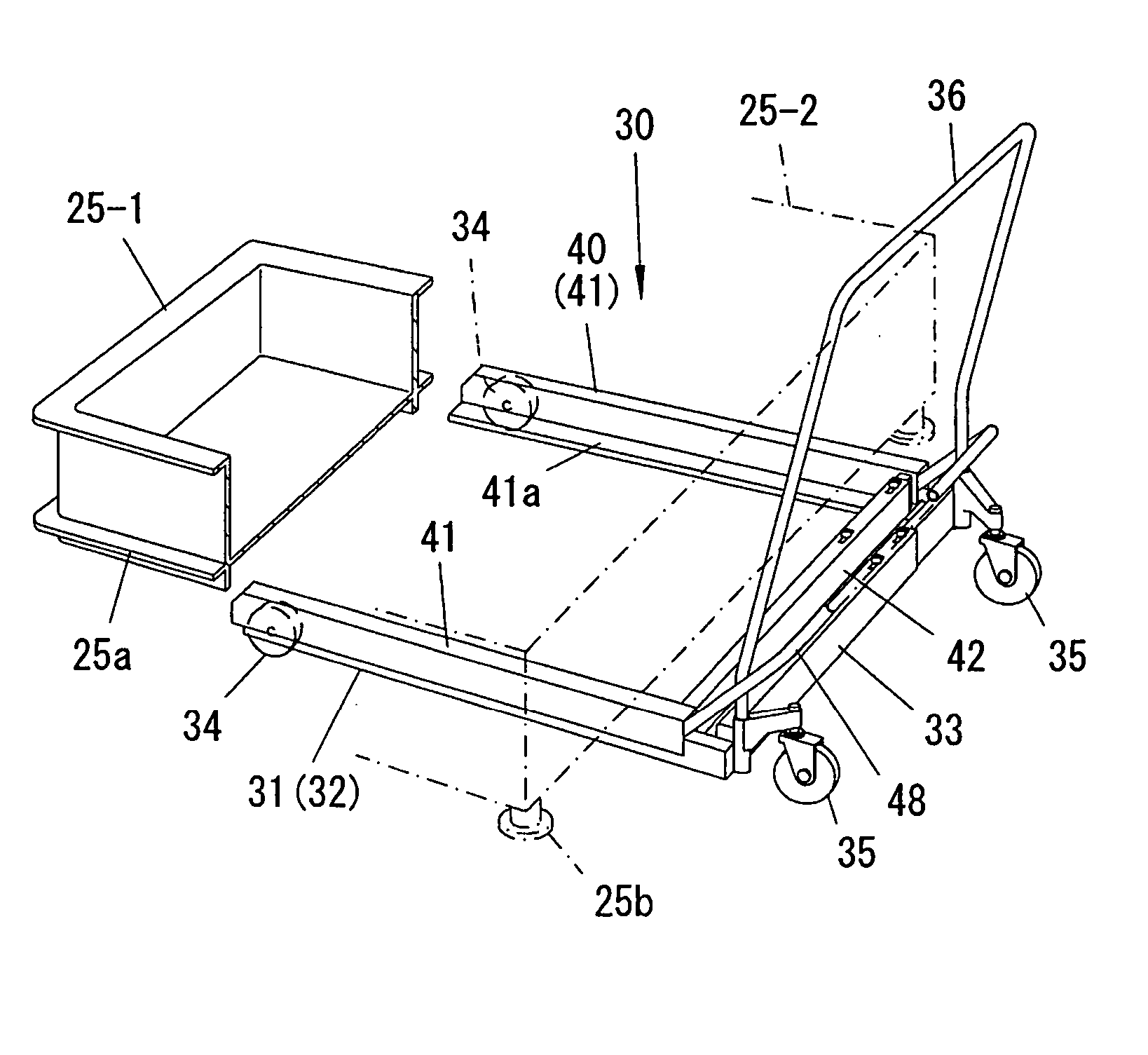
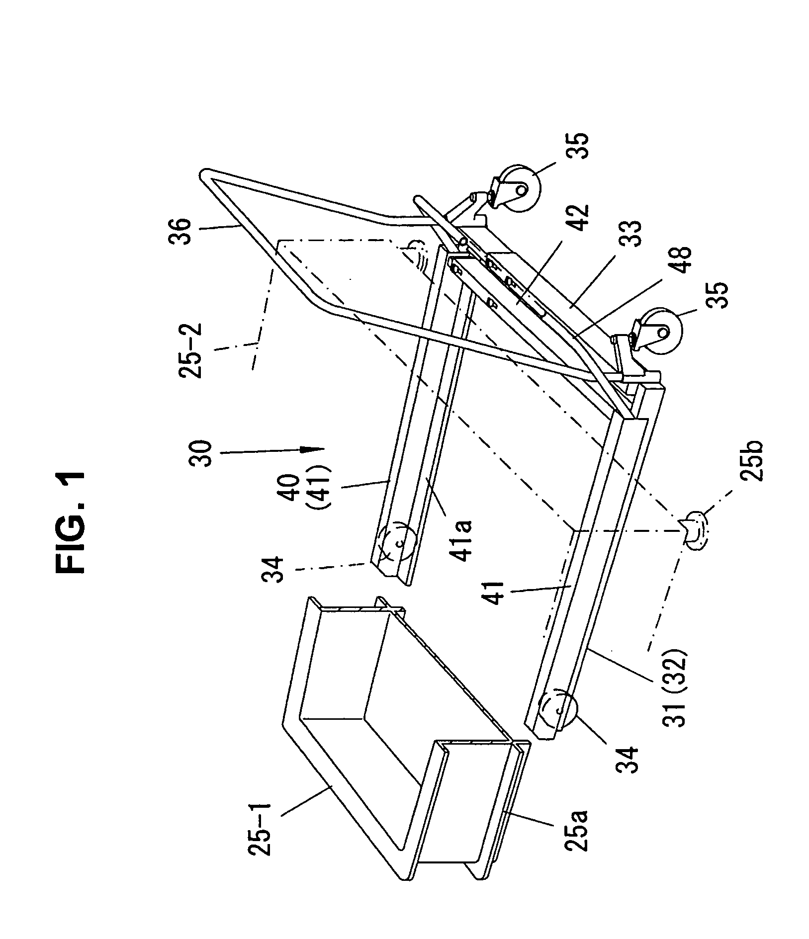
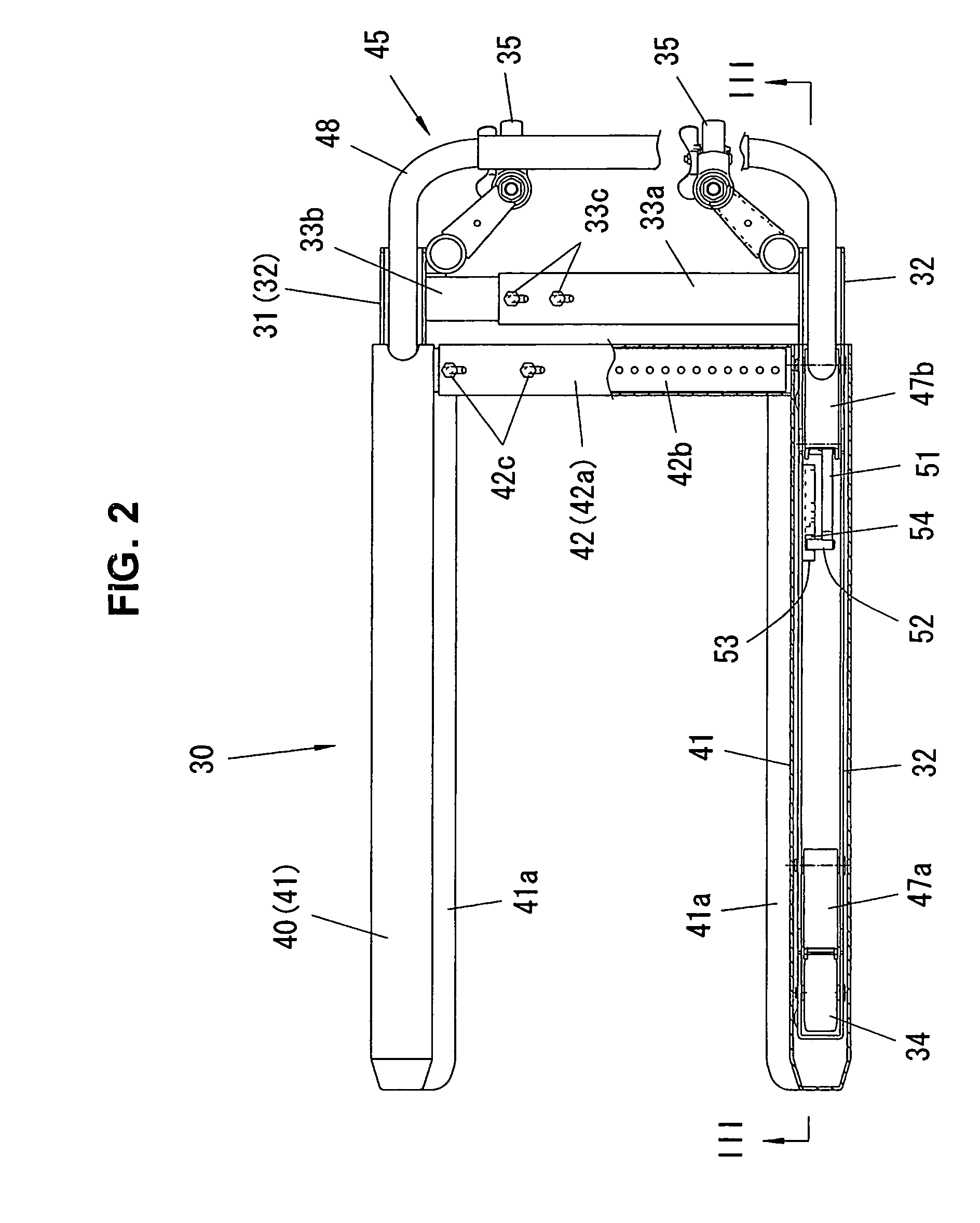
[0029] A description will be given of an embodiment in accordance with the present invention with reference to the accompanying drawings. In the drawings, FIG. 1 is a perspective view showing an embodiment in accordance with the present invention, FIG. 2 is a partly cross sectional plan view, FIG. 3 is a cross sectional view along a line III-III in FIG. 2 showing a state of a hoist table being lowered, FIG. 4 is a cross sectional side view showing a state of the hoist table being lifted, FIG. 5 is a cross sectional view showing a state of the hoist table being kept lifted, FIG. 6 is a cross sectional view showing a state of a locking apparatus being disengaged, and FIG. 7 is a cross sectional view of a main portion showing a state of the engagement apparatus being returned to an initial position.

[0030] In FIGS. 1 and 2, reference numeral 30 denotes a truck with a hoist, and reference numeral 31 denotes a frame thereof. The frame 31 is formed in a fork shape with an open front porti...


PUM


Abstract

For higher durability and easier assembly, a locking apparatus holding and releasing an ascended position of a hoist table, is structured such that engagement arms are connected to upper end portions of link arms connected to hoist table side of a parallel link mechanism to freely oscillate frontward, engagement bodies are provided in front end portions of the engagement arms, annular guide grooves guiding the engagement bodies in longitudinal and vertical directions are provided in side portion frames of a fork frame, a stopper walls having step shaped rear portions are provided in upper portions of the grooves, and front portions of the grooves are provided with check valves allowing the engagement bodies to pass through forward and guiding the passed engagement bodies to upper portion side of the guide grooves.

Description

TECHNICAL FIELD [0001] The present invention relates to a locking apparatus of a truck with a hoist for lifting and carrying a box container in which small articles such as parts, foods or the like are contained. BACKGROUND ART [0002] As a prior art, there has been a structure shown in FIGS. 8 to 10. In FIGS. 8 to 10, reference numeral 1 denotes a truck with a hoist, and reference numeral 2 denotes a frame thereof. The frame 2 is formed in a fork shape with an open front portion, by a pair of side portion frames 2a and 2a, which are apart from each other at the right and the left, and a cross frame 2b coupled to rear portions thereof (a right portion in FIG. 8), front wheels 3 and 3 are attached to front portions of the respective side portion frames 2a and 2a, and rear wheels (casters) 4 and 4 and a handle 6 are attached to both right and left end portions of the cross frame 2b. [0003] A fork-shaped hoist table 5 is fitted to the frame 2 from the above so as to be movable upward an...

Claims


Application Information

Patent Timeline
IPC IPC(8): B60P1/02
CPCB62B2206/02B62B3/0643
Inventor AONO, KOJI
Owner AONO CO LTD
Why Eureka
Try Eureka