A method and apparatus for fluid density sensing

Inactive Publication Date: 2006-11-09
OPW FUELING COMPONENTS
View PDF8 Cites 42 Cited by
  • Summary
  • Abstract
  • Description
  • Claims
  • Application Information

AI Technical Summary

Benefits of technology

[0009] Another exemplary embodiment of an apparatus for sensing the density of a fluid includes a shaft adapted to be positioned in a fluid within a container. A float assembly is disposed on the shaft and includes a mounting plate secured to the shaft, a spring having first and second ends, the first end adapted to engage the mounting plate, and a float adapted to engage the second end of the spring and capable of movement along the shaft. The apparatus further includes a displacement sensor having a magnetostrictive waveguide disposed along the shaft, a magnet operatively coupled to the float for movement therewith and in operative relation to the magnetostrictive waveguide, and pulsing and detection apparatus for detecting a position of the magnet along the waveguide, wherein the apparatus is configured to sense the density of the fluid based on the position of the float. The apparatus may further include at least one product float to sense the level of the

Problems solved by technology

Such manual processes, however, may give rise to errors in the calculations.
For example, discrepancies between the fluid's actual density and the system's input density may stem from many sources including: keystroke errors, entry of an approximate density for the particular fluid, incorrectly reading a separate density measuring device, measuring the density of a fluid sample that is not representative of the fluid in the tank (such as a sample taken from the delivery tanker), and others.
These errors in the den

Method used


Image

  • A method and apparatus for fluid density sensing
  • A method and apparatus for fluid density sensing
  • A method and apparatus for fluid density sensing

Examples


Embodiment Construction

[0018] Reference will now be made in detail to various embodiments of the invention, examples of which are illustrated in the accompanying drawings, wherein like numerals indicate similar elements throughout the views.

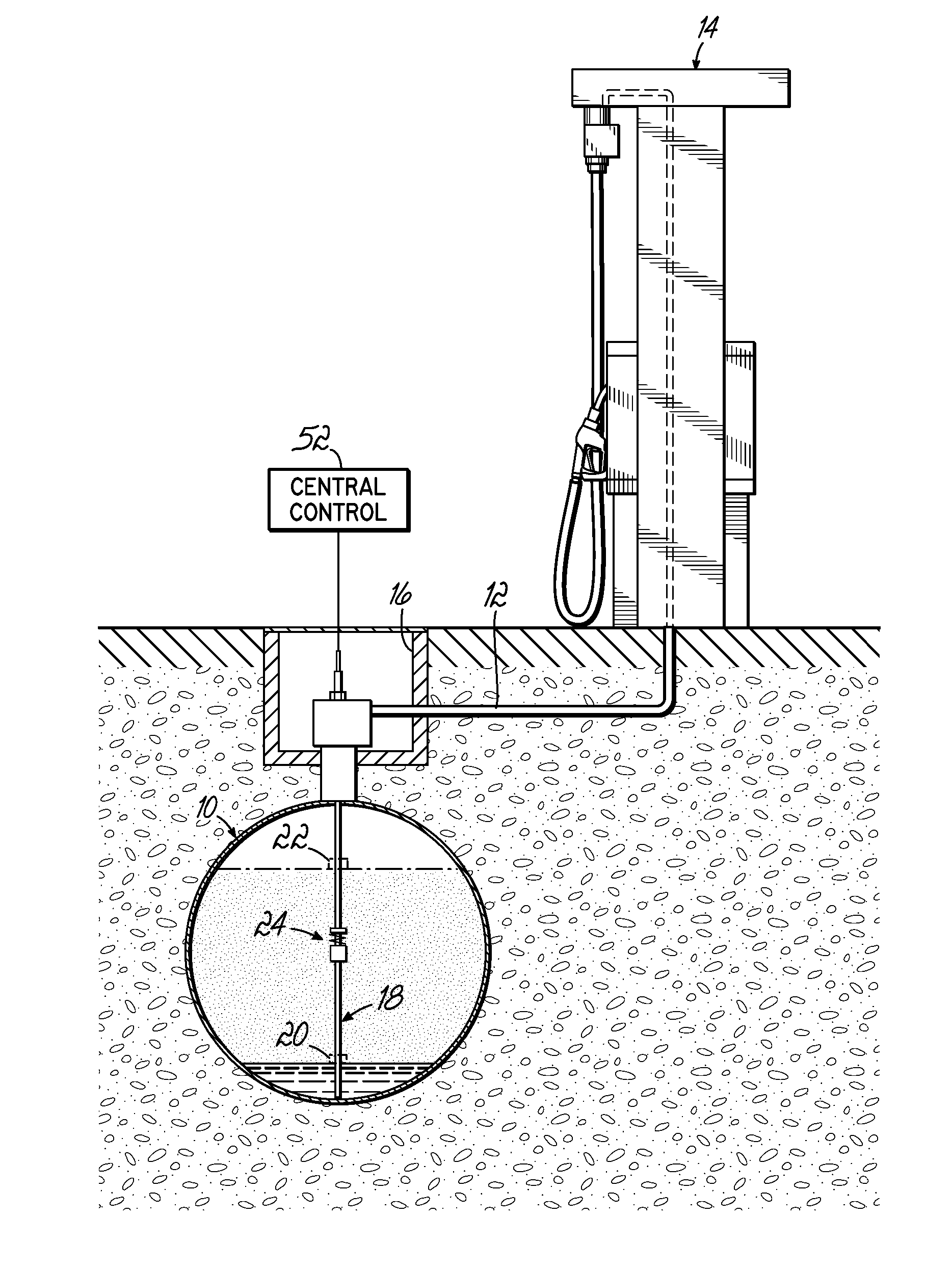
[0019] An exemplary fuel dispensing system is shown in FIG. 1 and generally includes an underground storage tank (“UST”) 10 for storing a fuel, a submersible pump (not shown), and a fluid conduit line 12 that transports the fuel under pressure to one or more dispensing units 14. Typically, the fluid conduit line 12 is coupled to the submersible pump via a pump manifold 16 that is typically located external to the tank 10, such as in a covered manway. As mentioned above, to meet EPA regulations, the integrity of the tank 10 must be regularly tested and the amount of any fuel leakage thererfrom monitored.

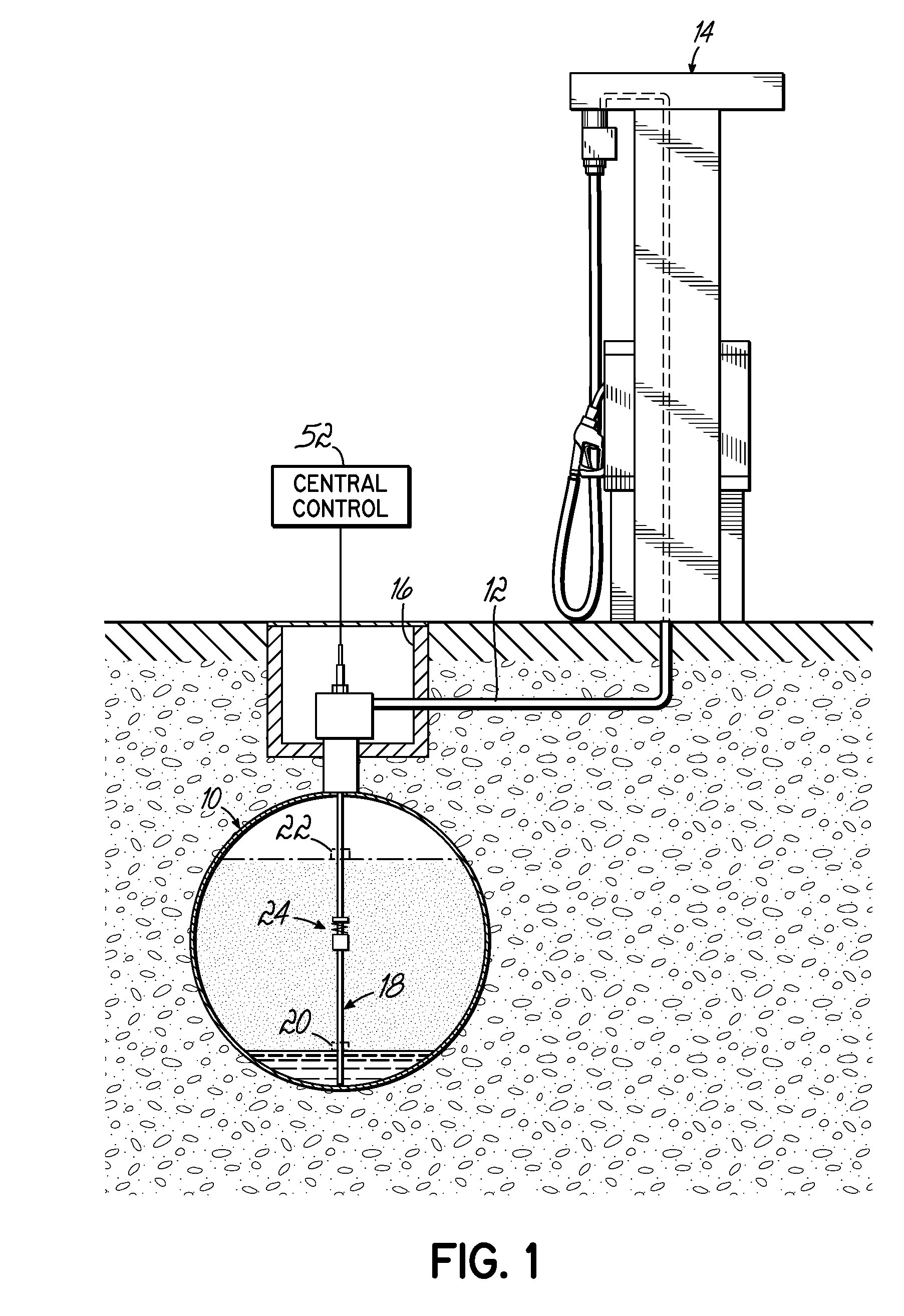
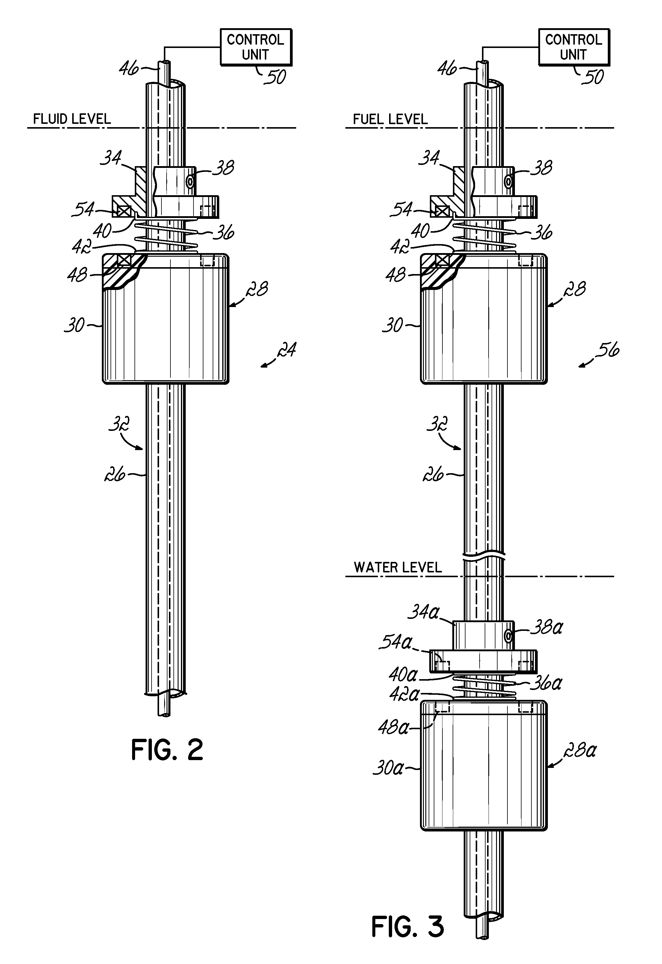
[0020] To this end, the dispensing system typically includes a product level probe 18 inserted through a port in manifold 16 and having one or more product floats for ...


PUM


Abstract

Methods and apparatus for measuring density of a fluid. The apparatus includes a shaft adapted to be positioned within a fluid and a biased float disposed on the shaft and capable of movement along the shaft. The apparatus further includes a displacement sensor for detecting a position of the float along the shaft. A method of sensing the density includes positioning the biased float in the fluid and sensing the position of the float to obtain data representative of the density of the fluid.

Description

[0001] This application claims priority to provisional patent application Ser. No. 60 / 679,261 filed on May 9, 2005, the disclosure of which is expressly incorporated by reference herein in its entirety.FIELD OF THE INVENTION [0002] The present invention generally relates to methods and apparatus for fluid density sensing. More particularly, the present invention relates to methods and apparatus for sensing or measuring density of a fluid within a container such as a storage tank using a spring-biased float and displacement sensor configured to sense the density of the fluid based upon the position or displacement of the float. BACKGROUND OF THE INVENTION [0003] There are many conventional applications requiring the measurement of fluid parameters, such as fluid level, within containers. One exemplary application is storage tanks (both above ground and underground) used to store fuel. For example, most gasoline stations have one or more underground storage tanks below ground to store...

Claims


Application Information

Patent Timeline
IPC IPC(8): G01N9/00
CPCG01F23/2963G01F23/0038G01N9/18G01F23/64
Inventor JARVIE, IAN F.
Owner OPW FUELING COMPONENTS
Why Eureka
Try Eureka