
Portable screening device

Inactive Publication Date: 2006-11-09
ORBACH DAVID M
View PDF10 Cites 9 Cited by
  • Summary
  • Abstract
  • Description
  • Claims
  • Application Information

AI Technical Summary

Benefits of technology

[0007] One object of the present invention is to provide means whereby a roadside accident scene may be rapidly and effectively shielded from the view of passing motorists.
[0008] Another object of the invention is to provide a screen and supporting equipment that can be conveniently carried by an emergency vehicle and readily erected in position to prevent travelers from viewing the accident scene and any associated rescue and clean-up activities.
[0009] A further object of the invention is to provide a screen for the purpose indicated, which is preferably made of a thin, light-weight material and is adapted to be carried by emergency vehicles in a compact condition.

Problems solved by technology

Under present-day traffic conditions on express roads and highways, particularly in inclement weather, it is a common occurrence that a more or less serious accident becomes the cause of traffic jams and / or additional accidents due to the fact that other travelers slow down or even stop in the vicinity of the original accident scene in order to view the scene or, perhaps, in some cases to bring assistance to victims.
Several devices have tried to provide solutions to this problem, each with limited success.
Unfortunately, none of these devices is truly portable because they require the use of heavy bases or mounting blocks to secure the screen housings.
In addition, these devices require specialized equipment or installation, such as special brackets or mounting posts, and they cannot be used effectively if these items are not present.
Moreover, none of these devices allows the user to increase the view shield area vertically to provide enhanced screening above the level of the adjacent screens, for example where the area to be screened is lower than the view area or can be viewed by motorists with a higher vantage point.

Method used


Image

  • Portable screening device
  • Portable screening device
  • Portable screening device

Examples


Embodiment Construction

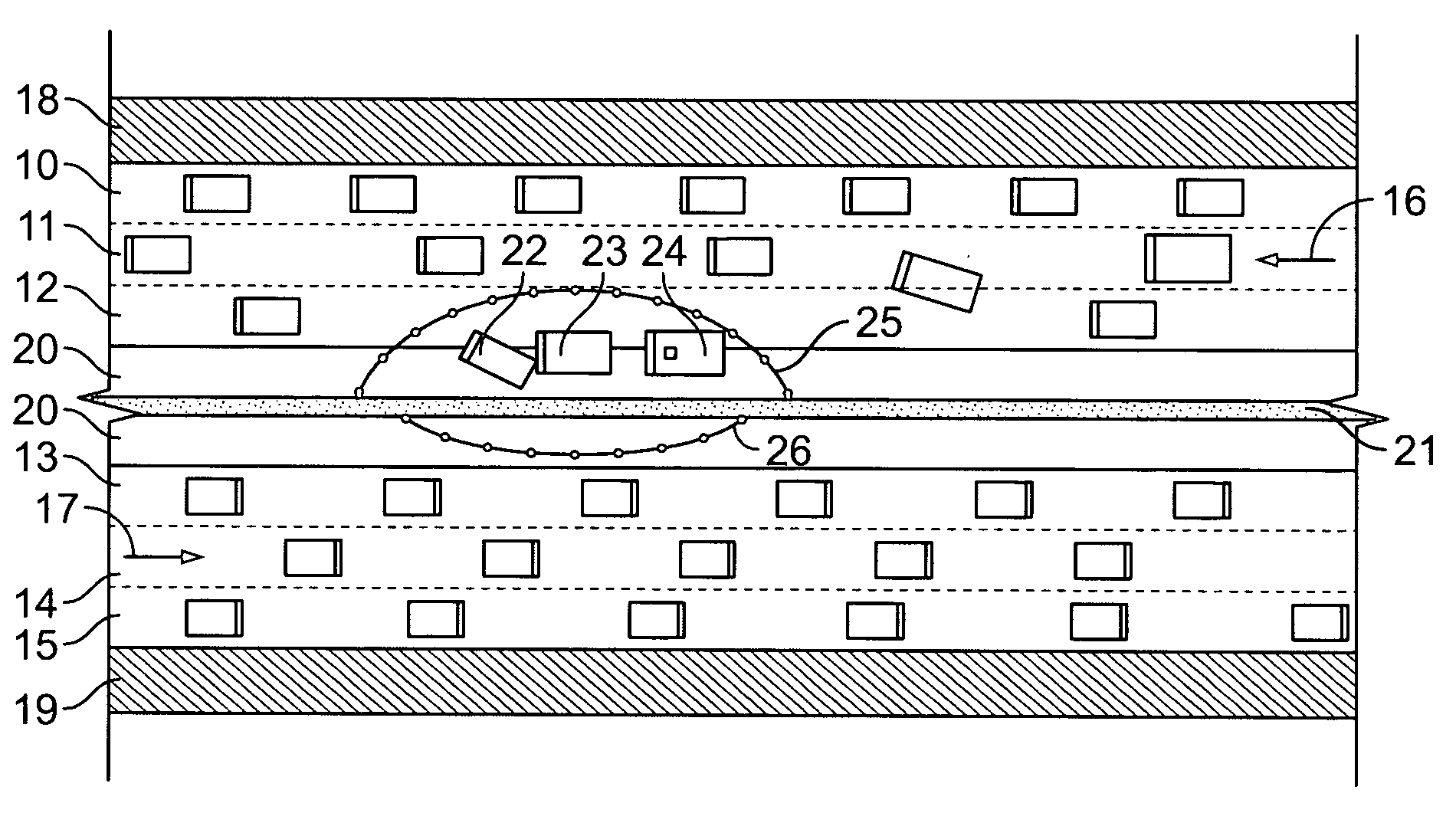
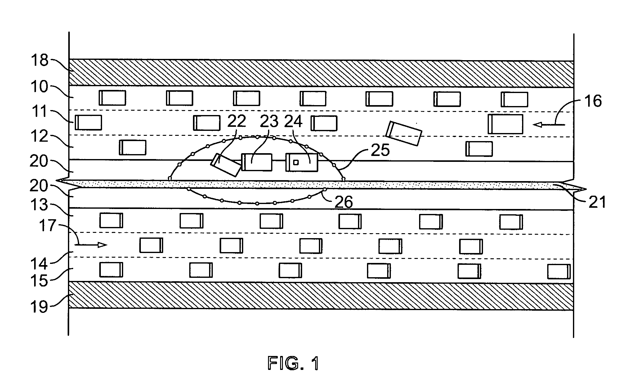
[0021]FIG. 1 shows a section of an expressway with three traffic lanes 10, 11, 12 in one direction and three traffic lanes 13, 14, 15 in the opposite direction, as indicated by arrows 16 and 17, respectively. Outside of lane 10 there is one shoulder 18 and outside of lane 15 is another shoulder 19, while the space between lanes 12 and 13 is occupied by dividing region 20, such as a double shoulder that could also be divided longitudinally by a barrier 21.

[0022]FIG. 1 depicts the scene of an accident wherein an automobile 22 traveling in lane 12 was hit from behind by another automobile 23, causing both vehicles to be partially thrown out of lane 12 onto the shoulder 20, both vehicles in this example shown remaining in upright position. One or more occupants of the vehicles may have sustained injuries and, perhaps, have been thrown to the ground. Even if the two vehicles 22, 23 directly involved in the accident have come to a halt entirely on the shoulder 20, the drivers of vehicles...


PUM


Abstract

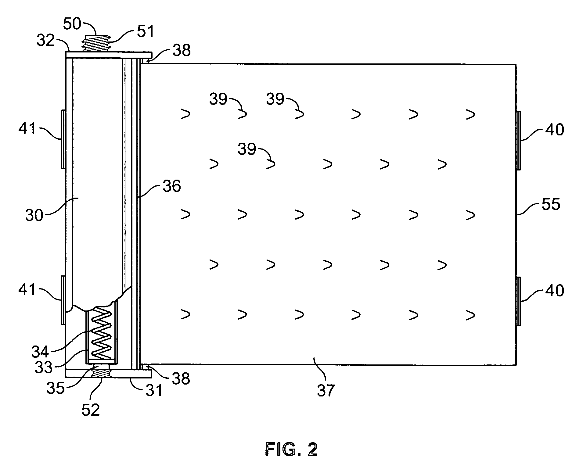
A screening device has elongate sheet of a thin non-transparent material windably mounted at one end to a spring-activated rotatable rod within a portable housing having a longitudinal slot through which the sheet is movable for winding and unwinding purposes while being prevented from passing entirely into said container through said slot. The container is provided at one end thereof with means for readily and releasably connecting the same in an upright position with a stationary object, while a supporting post is connectible to said sheet at the free end thereof and adapted to be secured to a stationary object at a distance from said first mentioned stationary object to thus support the unwound sheet in a substantially vertical position.

Description

BACKGROUND OF THE INVENTION [0001] This invention relates to means for enhancing road traffic safety by preventing accidents, delays and other complications frequently caused by curiosity and unwarranted activities on the part of travelers on a roadway passing the scene of a previous accident that is under clean-up and investigation by rescue and law enforcement personnel. [0002] Under present-day traffic conditions on express roads and highways, particularly in inclement weather, it is a common occurrence that a more or less serious accident becomes the cause of traffic jams and / or additional accidents due to the fact that other travelers slow down or even stop in the vicinity of the original accident scene in order to view the scene or, perhaps, in some cases to bring assistance to victims. This is the case both on the side of the road where the accident occurred and on the side of the road opposite to where the accident occurred. Such behavior frequently continues even after the ...

Claims


Application Information

Patent Timeline
IPC IPC(8): A01K29/00
CPCE01F13/028E01F7/00
Inventor ORBACH, DAVID M.
Owner ORBACH DAVID M
Learn More