Interchangeable simulated neon light tube assemblies and related accessories for use with lighting devices

a technology of neon lights and tubes, which is applied in the direction of vehicle interior lighting, transportation and packaging, lighting and heating equipment, etc., can solve the problems of affecting the performance of neon lights, affecting the safety of neon lights, and being difficult to break,

Inactive Publication Date: 2006-11-09
HEROLD DESIGN GROUP
View PDF27 Cites 25 Cited by
  • Summary
  • Abstract
  • Description
  • Claims
  • Application Information

AI Technical Summary

Benefits of technology

[0014] Still another aspect of the present invention provides a mounting assembly for attaching a light tube assembly to a fixed mounting surface, the mounting assembly comprising a mounting bracket attached to the fixed mounting surface and having opposed arms for receiving at least one end of the light tube assembly therebetween; and at least one light source disposed between the opposed arms of the mounting bracket and aligned in a manner to emit light through the one end of the light tube assembly secured in the mounting assembly, such that the light tube assembly will be illuminated.

Problems solved by technology

Unfortunately, neon lighting does have some drawbacks.
This may not only be costly, but can also be somewhat dangerous if not performed properly.
Because the tubes in which the neon gas is held are made of glass, such tubes are often considered fragile and easily breakable.
This presents still another danger to the user of neon lighting, and therefore, neon lighting devices are not recommended as toys for children.
In addition, when compared to other types of lighting, neon lighting is quite expensive, especially when the neon lighting is made into a custom design.
While some of these efforts have been partially successful, the results are often efficient or achieved through more difficulty, complexity and expense than actual neon.
Moreover, some of these efforts have failed to produce a substantially uniform distribution of light along the entire length of the tube.
However, optical fibers disadvantageously must be disposed within the light tube and are, therefore, also susceptible to breakage.
For example, prior art simulated neon light tubes, like all light tubes, are still susceptible to being broken.
Even though they are not necessarily made of glass and are not as easily broken as neon light tubes for neon lighting devices, they still be may be cracked or otherwise destroyed.

Method used


Image

  • Interchangeable simulated neon light tube assemblies and related accessories for use with lighting devices
  • Interchangeable simulated neon light tube assemblies and related accessories for use with lighting devices
  • Interchangeable simulated neon light tube assemblies and related accessories for use with lighting devices

Examples


Embodiment Construction

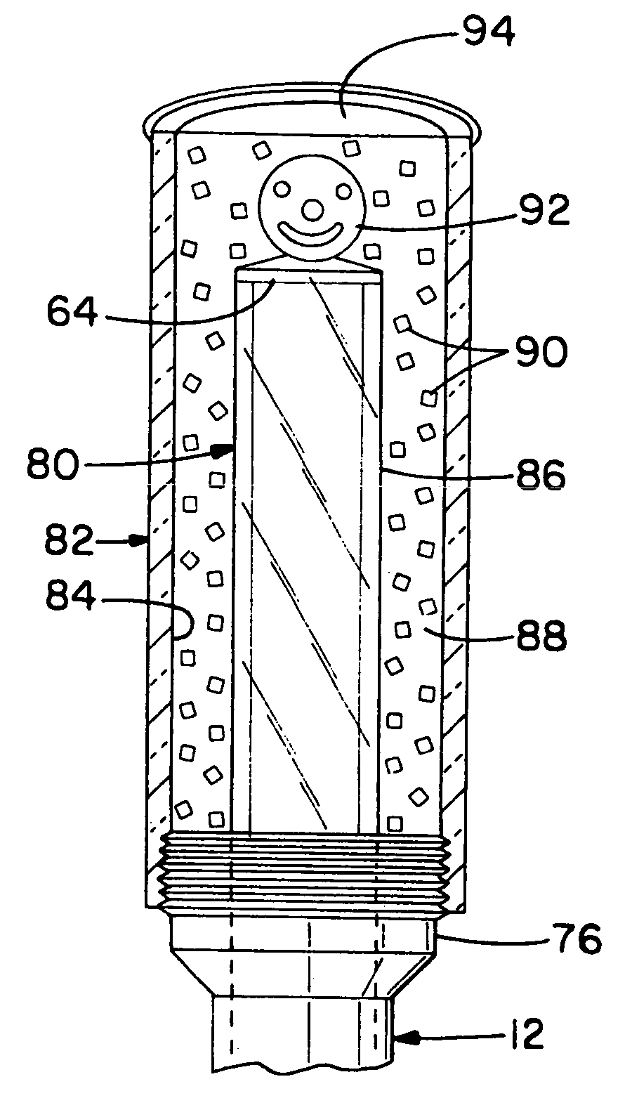
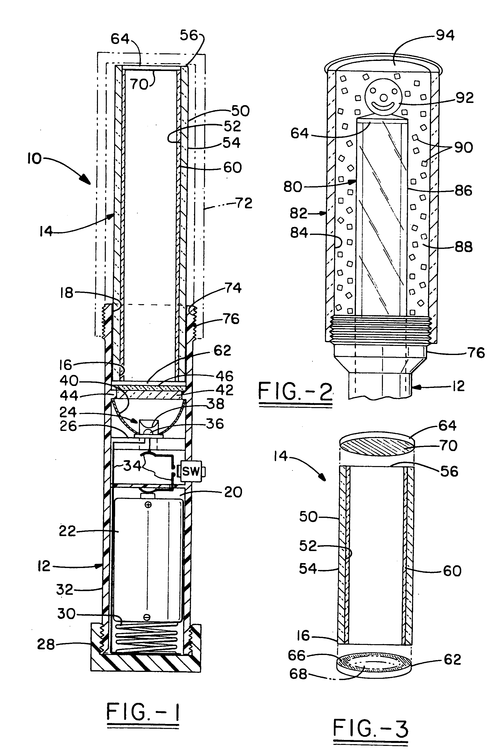
[0025] One representative embodiment of a lighting device according to the concepts of the present invention is generally designated by the numeral 10 in FIG. 1 and may include a handle or base portion, generally designated by the numeral 12, and an elongated, simulated neon light tube assembly, generally designated by the numeral 14. In the embodiment shown, one end 16 of the light tube assembly 14 is received within a tube-receiving end18 of the base portion 12 and is removably attachable to the base portion 12 by any means known in the art such as, for example, by frictional fit. Alternative embodiments where the light tube assembly 14 is removable from the base portion 12 provide for screwing the light tube assembly 14 into the base portion 12 or vice versa, for sliding the light tube assembly 14 into the base portion 12 via frictional fit and maintaining the frictional fit via the use of an O-ring and / or a set screw, or for snapping the light tube assembly 14 into the end 18 of...


PUM


Abstract

A simulated neon light tube assembly includes an elongated tube having a light diffusing material disposed therein for simulating the appearance of neon lighting. The light tube is used in conjunction with a base portion having a light source disposed therein to provide a lighting device. The light tube assembly of the present invention is preferably closed ended, and is selectively removable from the base portion so that it can, therefore, be replaced easily with another light tube assembly. Modified retaining covers, retaining caps and mounting assemblies are also described.

Description

TECHNICAL FIELD [0001] The present invention relates generally to a simulated neon light tube assembly and its related components for use with various lighting devices. More particularly, the present invention relates to a closed-ended, simulated neon light tube assembly suitable for use in and selectively removable from a gasless lighting device. Various accessories such as modified retaining covers, modified retaining caps for reflecting light beyond the simulated neon light tube, and modified mounting assemblies are also presented. BACKGROUND ART [0002] Battery-operated, gasless lighting devices, such as flashlights, are commonplace throughout the world and well know in the lighting art. More recently, gasless lighting devices of the type having a light source, such as a light emitting diode (LED), disposed within a handle or base and an elongated light tube permanently affixed to the handle or base for generally directing light through the light tube from one end thereof have be...

Claims


Application Information

Patent Timeline
Patent Type & Authority Applications(United States)
IPC IPC(8): F21V15/00
CPCB60Q1/2615B60Q1/44B60Q1/2657
Inventor HEROLD, MICHAEL A.
Owner HEROLD DESIGN GROUP
Why Eureka
Try Eureka