
Method and system for signal detection using a reduced transmitter constellation

a transmitter constellation and signal detection technology, applied in the field of network communication, can solve the problems of increasing decoding complexity, limiting the achievement of good performance, and increasing exponentially with the size of the transmitter

Inactive Publication Date: 2006-11-09
AVAGO TECH WIRELESS IP SINGAPORE PTE
View PDF9 Cites 15 Cited by
  • Summary
  • Abstract
  • Description
  • Claims
  • Application Information

AI Technical Summary

Benefits of technology

"The present invention provides a detection method for signals in multi-path and multi-channel systems that offers efficient and low complexity with tradeoffs between performance and complexity. The method uses a detection technique called ZF restricted ML detection, which is a combination of a ZF detection and an ML detection process to isolate a single constellation point from the transmitter constellation. The method quantizes the received point in the single constellation space or another point obtained from the received point to some of the signal constellation points using a criterion, such as minimum Euclidean distance. The transmitted signal is then obtained by performing an ML-detection process on the reduced set of constellation points. The invention offers a solution for efficient and low complexity signal detection in multi-path and multi-channel systems."

Problems solved by technology

Each of these known schemes, however, have certain disadvantages, for example, in ML detection, the decoding complexity increases exponentially with the size of the transmitter constellation, while providing very good performance in terms of probability of error.
For schemes such as ZF detection the decoding complexity increases only linearly with respect to the size of the transmitter constellation whereas the performance greatly depends on the co-relation among the paths of the MIMO channel and therefore is limited in achieving good performance by itself.
The sphere detection scheme involves finding a subset of a received constellation to do an ML search and also doing various mathematical computations such as QR factorization on the channel matrix and therefore has increased complexity.
The K-best scheme generally cannot guarantee the survival of ML paths with overall possible candidate paths.
This is because the path metrics of the search-tree created sometimes cross each other and causes irreducible errors, which degrades the symbol error rate performance, even if the signal-to-noise ratio (SNR) is high.

Method used


Image

  • Method and system for signal detection using a reduced transmitter constellation
  • Method and system for signal detection using a reduced transmitter constellation
  • Method and system for signal detection using a reduced transmitter constellation

Examples


Embodiment Construction

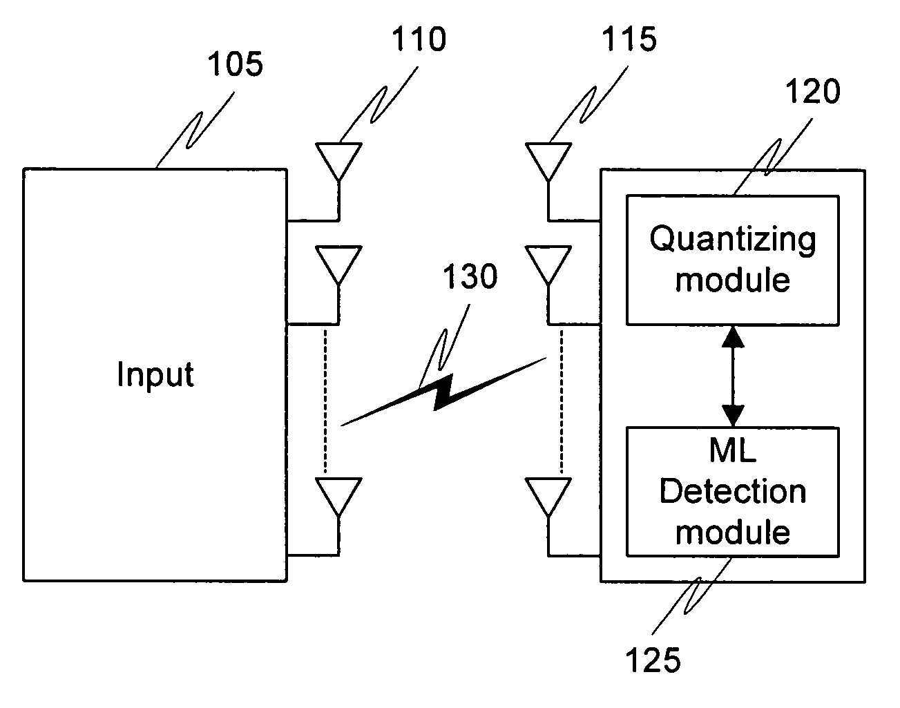
[0012] While embodiments may be described in many different forms, there are shown in the figures and will herein be described in detail certain specific embodiments, with the understanding that the present disclosure is to be considered as an example of the principles of the invention and not intended to limit the invention to the specific embodiments shown and described. Further, the terms and words used herein are not to be considered limiting, but rather merely descriptive. It will also be appreciated that for simplicity and clarity of illustration, common and well-understood elements that are useful or necessary in a commercially feasible embodiment may not be depicted in order to facilitate a less obstructed view of these various embodiments. Also, elements shown in the figures have not necessarily been drawn to scale. For example, the dimensions of some of the elements are exaggerated relative to each other. Further, where considered appropriate, reference numerals have been ...


PUM


Abstract

The present invention relates to a method, typically deployed on receivers deployed, for detecting a transmitted signal from a transmitter constellation by quantizing an altered signal to obtain a reduced constellation from the transmitter constellation (205), and then performing a maximum-likelihood detection scheme on the reduced constellation to obtain the transmitted signal (210). A system (120, 125) to perform the detection is also disclosed.

Description

RELATED APPLICATION DATA [0001] This application claims priority to and incorporates by reference India application serial number 323 / MUM / 2005 filed on Mar. 22, 2005, titled ZF restricted ML detection FIELD OF INVENTION [0002] The present invention relates generally to network communications, and more specifically to signal detection techniques in multi-path and multi-channel systems. BACKGROUND OF THE INVENTION [0003] As wireless modes of communication proliferate, the need to transmit at higher data rates is gaining importance. Several methods such as Orthogonal Frequency Division Multiplexing (OFDM) and Space Division Multiplexing offer greater spectral efficiency and superior tolerance in communication through multi-path channels.. Multi-path and MIMO (multiple-input-multiple-output) modes of communication are the generally preferred modes of communication as they provide better transmission rates, efficiency and accuracy. [0004] The transmitted signal needs to be accurately det...

Claims


Application Information

Patent Timeline
Patent Type & Authority Applications(United States)
IPC IPC(8): H04L23/02
CPCH04L2025/03624H04L25/03178
Inventor SHASHIDHAR, VUMMINTALARAJAN, BALAJI SUNDAR
Owner AVAGO TECH WIRELESS IP SINGAPORE PTE
Learn More