Retrofitting apparatus and method for securing roof frames against winds

a technology of retrofitting apparatus and roof frame, which is applied in the direction of structural elements, building components, and shock proofing, etc., can solve the problems of allowing walls to collapse, not being applicable to retrofitting existing roof frame structures, and high risk of damag

Active Publication Date: 2006-11-16
BUILDING PERFORMANCE AMERICAS
View PDF19 Cites 11 Cited by
  • Summary
  • Abstract
  • Description
  • Claims
  • Application Information

AI Technical Summary

Benefits of technology

[0010] One object of the present invention is to provide a retrofitting method and apparatus for reinforcement of roof frame structures against winds.
[0011] In accordance with one aspect of the present invention, there is an apparatus for reinforcement of an existing roof frame structure frame structure which comprises an elongate connector having an upper portion adapted to extend slantingly upward through a hole through a roof frame, allowing an upper end of the connector to protrude from a first side of the roof frame near a top edge thereof, and allowing a lower portion of the connector to extend downwardly from a second side of the roof frame such that a lower end of the connector can be secured to an underlying supporting structure. A head member is detachably connected to the upper end of the connector in order to prevent the roof frame from moving upward relative to the connector under an uplift force.
[0013] In accordance with a further aspect of the present invention, there is a reinforcement structure for roof frame retrofitting which comprises an elongate connector having an upper portion extending slantingly upward through a hole through a roof frame under a roof sheathing panel and a lower portion extending downwardly from a second side of the roof frame. The upper portion of the connector includes an upper end thereof protruding from a first side of the roof frame near a top edge of the roof frame. The lower portion of the connector includes a lower end thereof secured to an underlying wall. A head member is detachably connected to the upper end of the connector to prevent the roof frame from moving upward relative to the connector under an uplift force.

Problems solved by technology

Many millions of houses and small buildings are located in hurricane or tornado areas in, for example, the United States, at high risk of damage from the strong winds of hurricanes or tornadoes.
Recent studies of hurricane damage indicate that the most extensive damage to a house occurs when the roof is torn off, allowing the rain which often accompanies strong winds to ruin the contents of the house, and often allowing walls to collapse.
While prior art connectors of steel strip tie-down types excel as affordable connectors of roof structures to underlying walls in new construction of houses and small buildings, they are not as applicable when retrofitting existing roof frame structures.
These fittings pose difficulties in retrofitting applications because an upper portion of the steel-strip tie must extend over the top of a rafter / truss and down the other side in order to ensure adequate tie-down strength by applying the restraining force mainly at the top of the roof frame, as compression across the grain, which wood withstands quite well.
If the tie-down connectors are simply nailed into the side of the rafter / truss, as commonly done in the prior art, localized tensions are induced across the grain of the wood such that the rafter / truss member tends to split under high uplift conditions, which can release the connector's nails.
During retrofitting however, accessing the top portion of the rafter / truss requires removal and later restoration of an area of roofing and sheathing, which are laborious and costly operations, and thus tend to discourage such retrofit upgrading of the existing housing and building stock.
Frye's lag screws into the narrow edge of the rafter / truss would however invite splitting and cause tension failure.
Furthermore, only the screws near the junction of rafter / trusses with the top of the wall would contribute effectively, and the usual absence of a stud directly under a rafter / truss would leave Frye's wall lag screws rather ineffective.
All this entails laborious and uncertain sealing of the roof penetrations, and interferes with any subsequent re-roofing job.

Method used


Image

  • Retrofitting apparatus and method for securing roof frames against winds
  • Retrofitting apparatus and method for securing roof frames against winds
  • Retrofitting apparatus and method for securing roof frames against winds

Examples


Embodiment Construction

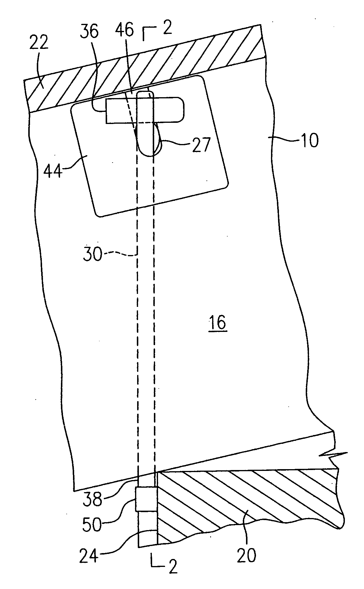
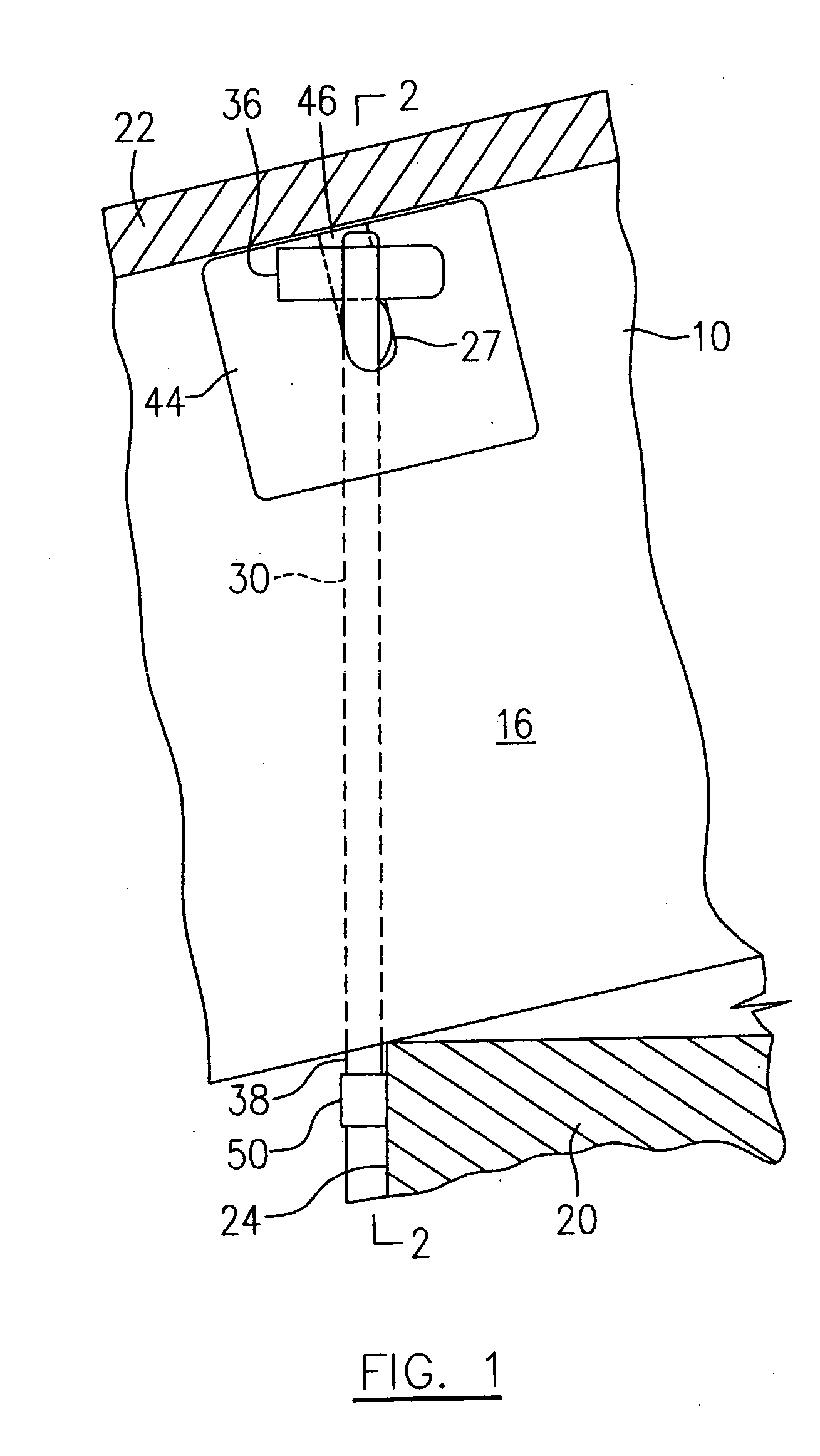
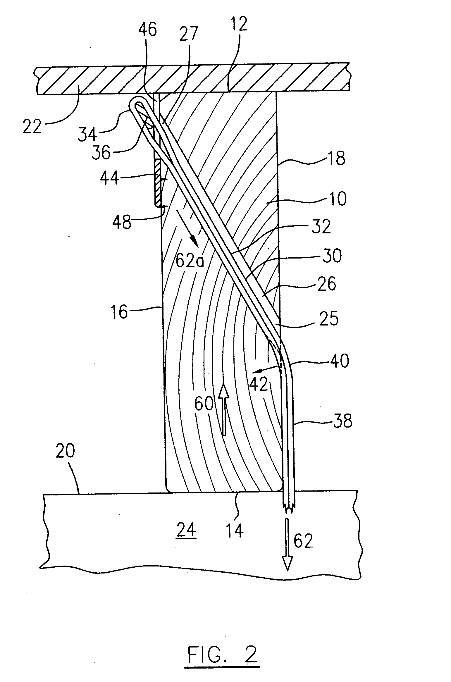
[0020]FIGS. 1 and 2 illustrate an existing wood roof frame structure incorporating one embodiment of the present invention for reinforcement of the existing roof frame structure in a retrofit job. In a wood roof frame structure, rafters and trusses are roof structural members and usually present similar rectangular cross sections. Rafters and trusses generally extend partially or wholly between exterior walls and provide locations for reinforcing the structure where rafters and trusses cross over such walls. In order to denote a roof structural member without the need for unnecessary distinction between rafters and trusses, such roof structural members are referred to as a roof frame throughout the text of this specification and the appended claims, and are indicated by numeral 10 in the drawings. The roof frame 10 has two opposed relatively narrow sides referred to as top and bottom edges 12, 14 and two opposed relatively wide sides referred to as first and second sides 16, 18 ther...


PUM


Abstract

An apparatus and method is provided for tying down an existing roof frame to resist windstorm uplift forces, in which an elongate connector is inserted slantingly upward through a hole through the roof frame, allowing an upper end of the connector to protrude from the roof frame to receive a head member which is detachably attached thereto in order to prevent the roof frame from moving upward relative to the connector under an uplift force. The lower end of the connector is secured to an underlying wall such that the connector applies a restraining force against wind uplift forces.

Description

TECHNICAL FIELD [0001] The present invention relates to reinforcement of wood roof structures of houses and low-rise buildings, and more particularly to a retrofitting apparatus and method for securing wood roof frames against winds. BACKGROUND OF THE INVENTION [0002] Many millions of houses and small buildings are located in hurricane or tornado areas in, for example, the United States, at high risk of damage from the strong winds of hurricanes or tornadoes. Recent studies of hurricane damage indicate that the most extensive damage to a house occurs when the roof is torn off, allowing the rain which often accompanies strong winds to ruin the contents of the house, and often allowing walls to collapse. [0003] There is a great need for affordable retrofitting methods for reinforcement of wood roof frames. While prior art connectors of steel strip tie-down types excel as affordable connectors of roof structures to underlying walls in new construction of houses and small buildings, the...

Claims


Application Information

Patent Timeline
Patent Type & Authority Applications(United States)
IPC IPC(8): E04B1/38
CPCE04G23/0218E04B7/04E04G2023/0248Y10S52/11
Inventor PLATTS, ROBERT E.
Owner BUILDING PERFORMANCE AMERICAS
Why Eureka
Try Eureka