
Containment system for and method of blast mitigation in varied environmental settings

a technology of environmental environment and containment system, which is applied in the field of explosive blast mitigation enclosures, can solve the problems of increasing the risk to the first responder and the immediate surroundings, reducing the blast overpressure energy, and increasing the risk of explosions

Inactive Publication Date: 2006-11-23
ALLEN VANGUARD
View PDF7 Cites 3 Cited by
  • Summary
  • Abstract
  • Description
  • Claims
  • Application Information

AI Technical Summary

Benefits of technology

"The present invention provides an improved containment system and method for blast mitigation. The system is adaptable to various environmental settings and can be easily moved to enclose explosive devices. The system includes a plurality of wall panels made of ballistic fabric that are removably attached to each other to form a floor-less enclosure. One of the wall panels has a closable flap allowing for the introduction of blast-suppression foam into the enclosure. The method involves positioning the blast mitigation enclosure around the explosive device and filling it with foam material to suppress the blast upon detonation of the device. The technical effects of the invention include improved safety and protection against blast-related accidents."

Problems solved by technology

When a blast occurs under blast-suppression foam, as each bubble bursts, there is an incremental loss of the blast overpressure energy, the net effect of millions of bubbles being destroyed causing a significant blast reduction.
The action of moving the suspect device increased the risk to the First Responder and the immediate surroundings.

Method used


Image

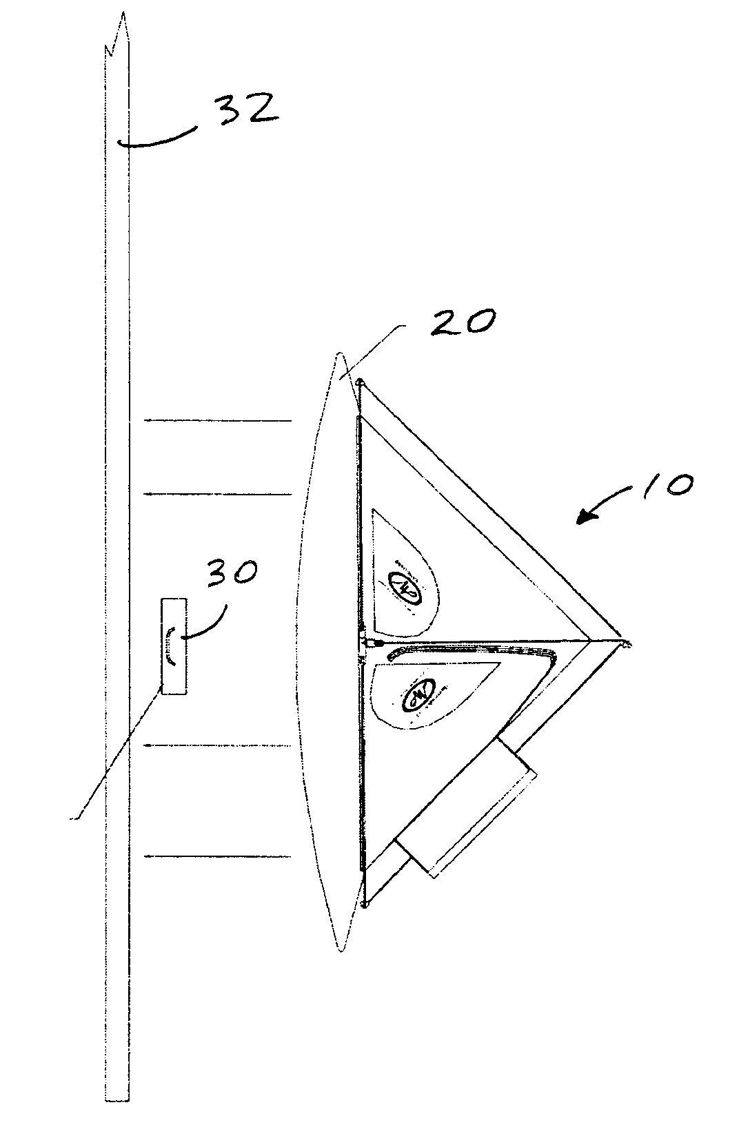
  • Containment system for and method of blast mitigation in varied environmental settings
  • Containment system for and method of blast mitigation in varied environmental settings
  • Containment system for and method of blast mitigation in varied environmental settings

Examples


Embodiment Construction

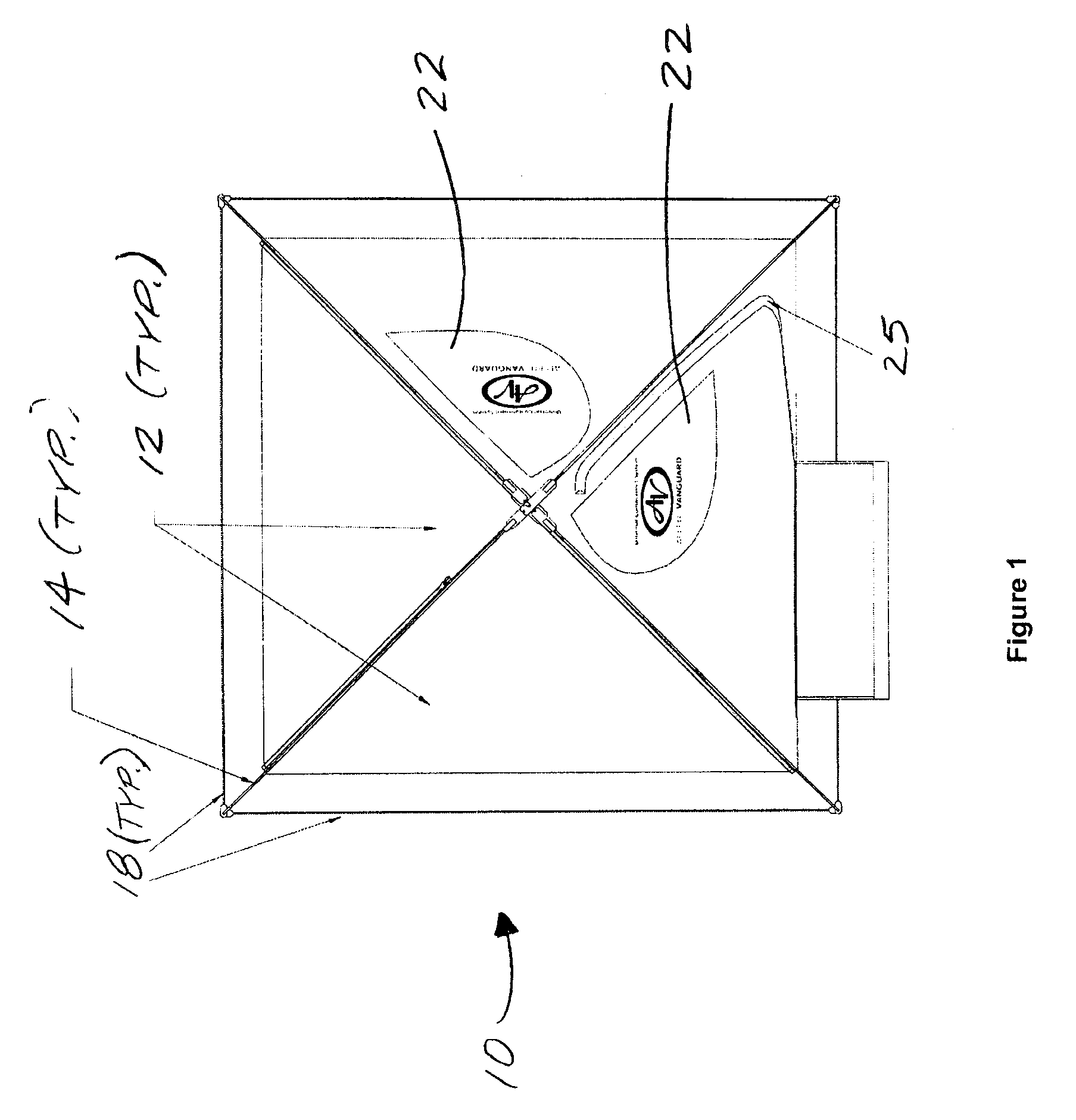
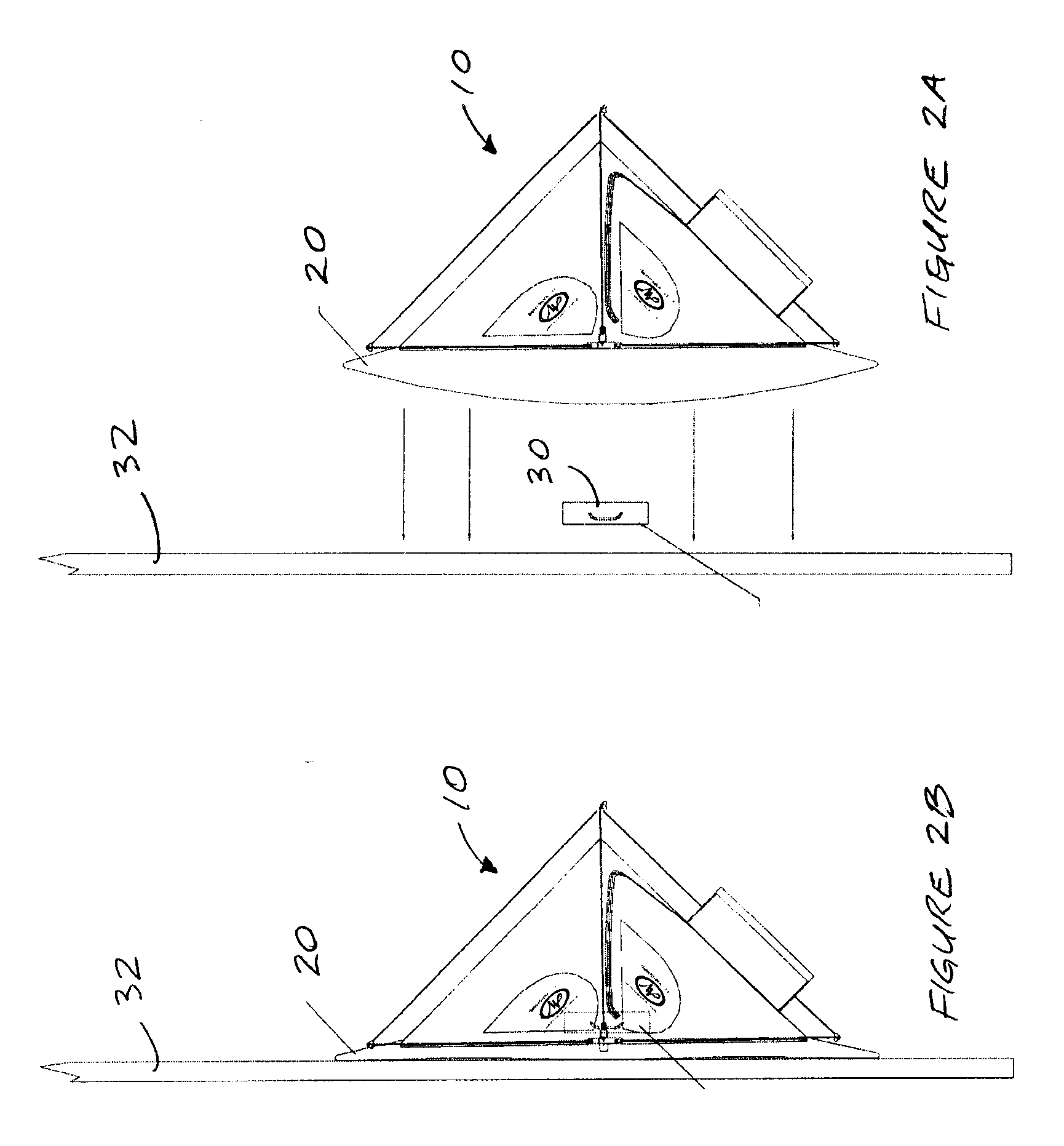
[0020] A containment system for and method of blast mitigation that addresses one or more of the problems in the art is presented in FIGS. 1 through 7.

[0021] The Adjustable Containment System (ACS) 10 will generally take the form of a tent or hemispherical, dome-shaped, 4- or 6-panel enclosure which will mitigate the blast of Chem-Bio, Radiological, or shrapnel producing devices. A 4-panel enclosure will generally be pyramid-like in shape with a square foot-print and 4 upstanding wall panels, more or less equal in dimensions. A 6-panel enclosure will have 6 equally-dimensioned wall panels and a hexagonal footprint.

[0022] The ACS 10 can be adjusted to accommodate suspect devices placed in various environmental settings such as against a wall, adjacent the outside corner of two walls meeting at 90 degrees, or in close proximity to an immovable object, without having to move the suspect device.

[0023] The wall panels of a typical UCS containment enclosure are sewed together so the en...


PUM


Abstract

The invention relates to explosive blast mitigation enclosures, and in particular to enclosures adaptable to accommodate blast mitigation of suspect devices placed against a wall, the outside corner of two walls meeting at 90°, in close proximity to an immovable object such as a telephone pole or in other similar environmental settings. One aspect of the invention is broadly defined as a blast mitigation enclosure adaptable to various environmental settings comprising a plurality of wall panels substantially fabricated from ballistic fabric. The wall panels are removably attached to one another along their adjacent upright edges to form a floor-less enclosure, and at least one of the wall panels has a closable flap allowing for the introduction of blast-suppression foam into the enclosure.

Description

FIELD OF INVENTION [0001] The invention relates to explosive blast mitigation enclosures, and to an apparatus and method for use therefor. More particularly, the invention relates to enclosures adaptable to accommodate blast mitigation of suspect devices placed against a wall, the outside corner of two walls meeting at 90°, in close proximity to an immovable object such as a telephone pole or in other similar environmental settings. BACKGROUND OF THE INVENTION [0002] Blast mitigation enclosures have been known for some time. One particular system, the UCS (Universal Containment System) from Allen-Vanguard, consists generally of a lightweight tent-shaped ballistic-fabric enclosure which can be placed over a suspect device and filled with a blast-suppression foam. The suspect device can then be detonated and the UCS will absorb the energy of the blast and contain contaminants that are released in the process. When a blast occurs under blast-suppression foam, as each bubble bursts, the...

Claims


Application Information

Patent Timeline
Patent Type & Authority Applications(United States)
IPC IPC(8): F42B33/00
CPCF42D5/045
Inventor DAVIS, JOHN
Owner ALLEN VANGUARD
Learn More