Multistage spinal fixation locking mechanism

Inactive Publication Date: 2006-11-23
KIC VENTURES LLC +1
View PDF69 Cites 241 Cited by
  • Summary
  • Abstract
  • Description
  • Claims
  • Application Information

AI Technical Summary

Benefits of technology

[0012] According to an aspect of the present invention, there is provided a locking mechanism configured to engage and lock a relative position of a bone fixation device and a relative position of a stabilization device. The locking mechanism comprises: a seat having a bottom portion configured to receive the fixation device and prevent the fixation device from passing entirely the

Problems solved by technology

In many cases, however, pseudoarthrosis is a problem, particularly in cases involving fusion across the lumbosacral articulation and when more than two vertebrae are fused together.
One of the main challenges associated with spinal fixation is securing the fixation device to the spine without damaging the spinal cord.
Of these factors, the most difficult to achieve may very well be providing easy surgical access when the implant is being deployed and / or removed by surgeon.
In use, it is difficult to maintain proper positioning of the fixation device while tightening a nut or other such locking mechanism.

Method used


Image

  • Multistage spinal fixation locking mechanism
  • Multistage spinal fixation locking mechanism
  • Multistage spinal fixation locking mechanism

Examples


Embodiment Construction

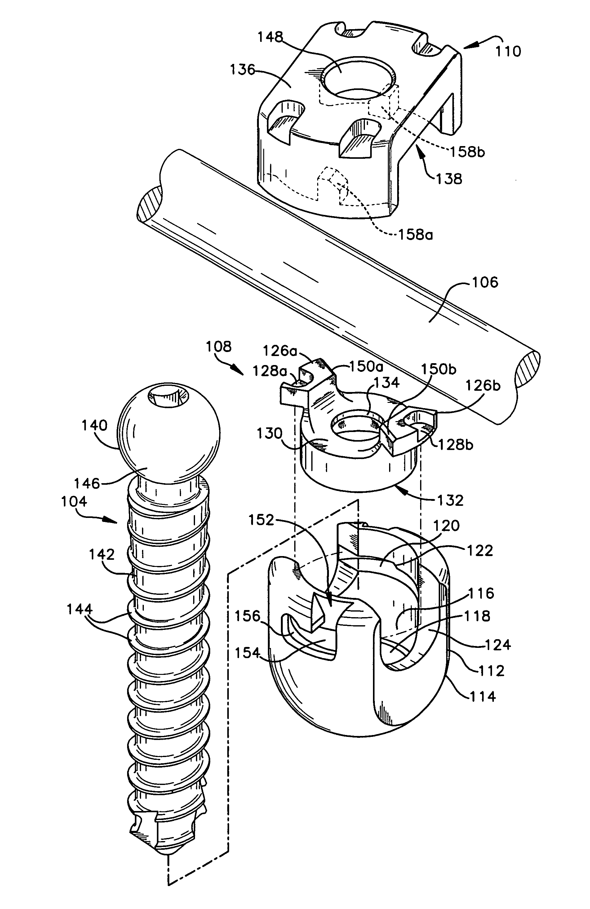
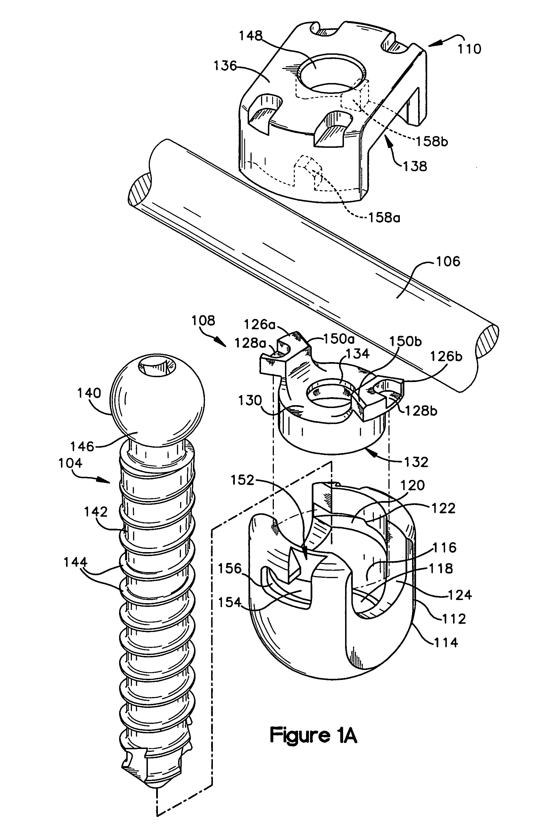
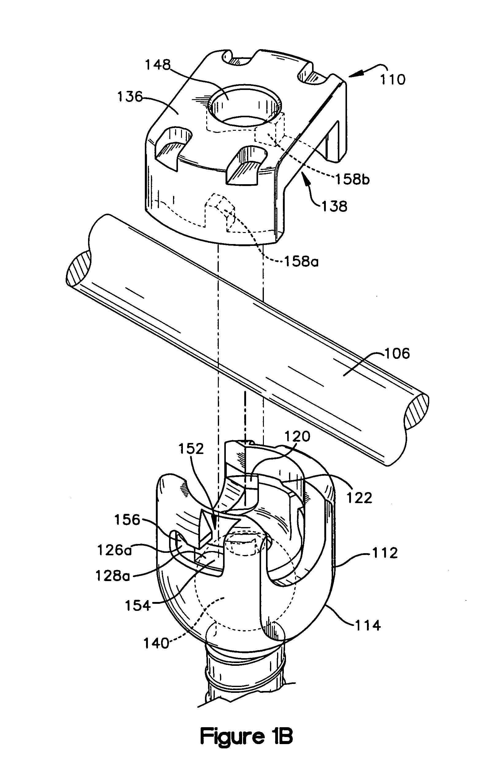
[0025] Turning initially to FIGS. 1A-C and 2A-D, FIGS. 1A-C show exploded perspective views of the locking mechanism of the present invention, and FIGS. 2A-D show cross sectional views of the locking mechanism of the present invention. The locking mechanism 100 is configured to engage and lock the relative position of a fixation device 104 with respect to the seat 102. The locking mechanism may also be configured to lock the relative position of the stabilization device 106 with respect to the seat 102. Preferably, the fixation device 104 can be locked independent of the stabilization device 106.

[0026] The locking mechanism 100 includes a seat 102, a washer 108 and a cap 110. The seat 102 includes a bottom portion 114 that is configured to receive the fixation device 104 such that a socket 116 of the bottom portion 114 engages part of the fixation device 104 and prevents the fixation device 104 from passing entirely therethrough.

[0027] The fixation device 104 may be, for example, ...


PUM


Abstract

The present invention relates to a locking mechanism and method of locking the relative positions of a fixation device like a bone screw and of a stabilization device like a rod. The locking mechanism includes a seat, a washer and a cap. The seat includes a bottom portion configured to receive the fixation device such that a socket of the bottom portion engages part of the fixation device and prevents the fixation device from passing entirely therethrough. The seat further includes a side portion configured to receive the stabilization device, a washer and a cap. When the washer and cap are fully engaged with the seat, the fixation device may be locked independent of the stabilization device. The locking mechanism may also include a locking element for locking the stabilization device.

Description

FIELD OF THE INVENTION [0001] The present invention relates generally to prostheses for treating spinal pathologies, and more specifically to a bone interface anchor for holding a stabilization rod. BACKGROUND OF THE INVENTION [0002] Various methods of spinal immobilization have been used in the treatment of spinal instability and displacement. The most common treatment for spinal stabilization is immobilization of the joint by surgical fusion, or arthrodesis. This has been known for almost a century. In many cases, however, pseudoarthrosis is a problem, particularly in cases involving fusion across the lumbosacral articulation and when more than two vertebrae are fused together. Early in the century, post operative external immobilization such as the use of splints and casts was the favored method of spinal fixation. As surgical techniques became more sophisticated, various methods of internal and external fixation were developed. [0003] Internal fixation refers to therapeutic meth...

Claims


Application Information

Patent Timeline
IPC IPC(8): A61F2/30
CPCA61B17/7032Y10T74/22A61B17/7037
Inventor BAKER, DANIEL R.THALER, CARLY A.KUNZLER, ALEX E.FINAZZO, ANTHONY V.
Owner KIC VENTURES LLC
Why Eureka
Try Eureka